

1. INTRODUCTION
2. STUDY ON CURRENT STATUS OF DOMESTIC TEST FACILITIES
3. ANALYSIS ON SPACE ENVIRONMENT TEST FACILITIES FOR LARGE SATELLITE
3.1. Analysis of Compact Payload Test Range facility
3.2. Analysis of Large Thermal Vacuum Test Facility
3.3. Analysis of Vibration and Static Load Test Facility
3.4. General requirement of assembly and test room facility
4. SECURITY MANAGEMENT STRATEGY
4.1. Organization of a test center for public-private partnership testing
4.2. Space Environment Test Facility Security Management: Concepts, Regulations, and International Case Studies
5. CONCLUSION
1. INTRODUCTION
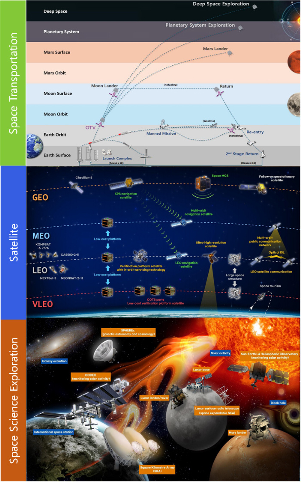
Within the Korea Space Development Promotion Plan, space development is being carried out in various fields, including space exploration, establishment of a foundation for the space industry, development of public satellites such as geostationary complex satellites and Korean navigation satellites, and development of observation satellites for space security (Fig. 1) [1]. Due to these development plans, it is expected that space environment testing will continuously be required for satellite systems in the coming years.
In order to meet the demand for testing in the various fields, related infrastructure is being built by the government and private sectors. Satellites are categorized into micro-satellites, small satellites, medium-sized satellites, and large satellites according to their weight, and the specifications of the test facilities required vary depending on the size of the satellite. Depending on the weight and mass of the satellite, the size of the space required for proper testing, the size of the test equipment, and the performance of the test equipment all vary.
In particular, space environment test facilities with larger, more effective space which achieve higher performance are required to perform system environmental tests for large satellites that will be required in the future.
In particular, in the case of space environment test facilities for the verification of large satellites, it is essential to jointly utilize the private sector and the government to secure the economical investment of the national budget and the expertise of the operating personnel. Space environment test facilities for the verification of large satellites are designed to perform system-level tests on large satellites, so they cannot perform tests on small and medium-sized satellites and components. While some are technically possible, they are not cost-effective. For satellite components and small satellites, the number and variety of test items is large and varied, but the technical aspects of performance verification are all better suited to be performed in smaller test facilities. Therefore, large test facilities are very inefficient in terms of utilization if they are only used by a specific organization. This can be seen by looking at the current state of space environment test facilities overseas. In Europe, IABG in Germany, Airbus in France, and Thales in Italy have built and operated space environment test facilities, but in the case of large space environment test facilities, they are built and jointly utilized at ESTEC under the European Space Agency.
In this paper, we identified additional test facilities required to perform space environment tests for large systems to be developed in the future and reviewed the construction plan. In addition, we discussed the deployment and security management strategy of the test facility for public-private joint utilization.
2. STUDY ON CURRENT STATUS OF DOMESTIC TEST FACILITIES
In general, satellites weighing more than 1,000 kg are classified as large satellites. Currently, geostationary satellites developed in Korea weigh about 3,500 kg, hence Korea qualifying as possessing space environment test facilities for the verification of large satellites. However, in this study, we tried to identify the required test facilities in consideration of the planned large observation satellites and space exploration fields such as the James Webb Space telescope recently launched by NASA. Based on this, the maximum shape of the test object was selected as 5 meters in diameter, 9 meters in height, and 5 tons in weight.
Space environment test facilities are categorized into launch environment, orbital environment, and assembly room as shown in Fig. 2.
In this research, we conducted a study on the current status of each facility and the construction plan of the required facility.
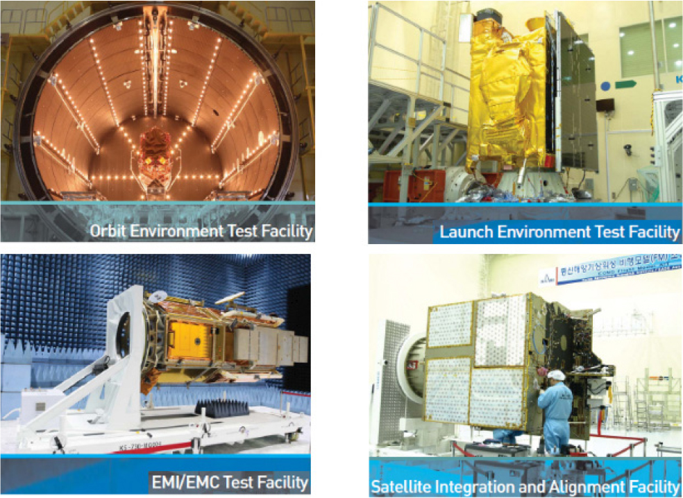
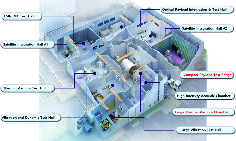
Currently, the space environment test facilities built and operated in Korea are KARI SSETC, KAI Space Center, KTL, and KAIST Satrec. Among these test facilities, the Korea Aerospace Research Institute (KARI) Satellite & Space Exploration Test Center (SSETC) can conduct various environmental tests for large satellites in one roof building. KARI SSETC was established in 1996 for the technological independence of satellites and launchers, and was built as a test facility which assembles and conducts environmental tests for small and medium-sized commercial satellites. Since then, the facility underwent three times of expansion due to the large size of satellites and is operated as a facility capable of performing environmental tests for large geostationary satellites as shown in Fig. 3.
In this paper, based on the space environmental test facility built at KARI SSETC, we will discuss the construction plan for additional test facilities required to perform the tests of the test objects defined above.
According to the analysis, additional test facilities to be secured were identified as a large thermal vacuum chamber (LTVC) for orbital environment testing, Compact Payload Test Range (CPTR) for payload verification of communication satellites, static load test facility for structural strength verification, and a large assembly hall. Design requirements were discussed for the above four test facilities.
3. ANALYSIS ON SPACE ENVIRONMENT TEST FACILITIES FOR LARGE SATELLITE
3.1. Analysis of Compact Payload Test Range facility
3.1.1. Survey of Test ranges
Fig. 4 shows a type of the test ranges measuring the antenna patterns and the characteristics of the payload parameters with antennas [2]. Outdoor ranges were mainly used in the early days, and Fig. 4(a), (b) shows an elevated and a slanted range. Fig. 4(c) shows in-door range allowing for directly measuring a far-field in an anechoic chamber, and Fig. 4(d) shows a compact antenna test range that can measure a far-field over a wide frequency band.
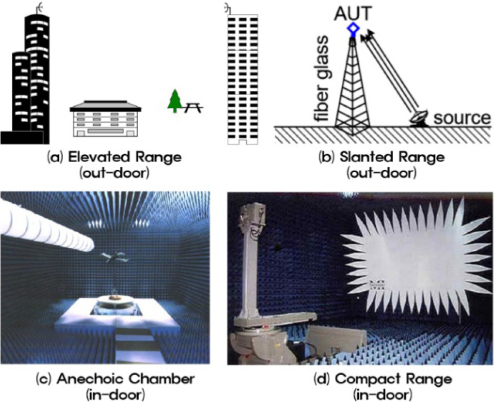
Test range have been developed to meet the increasingly complex satellite payloads and precise satellite systems. In particular, indoor range can be free from external environmental conditions such as climate conditions, radio environment, and system and service security, and in terms of technology, it enables precision measurements due to increased frequencies, use of high-speed data, high-performance antennas, and reuse of frequencies and polarizations.
3.1.2. Near-field Scanner
Basically, the antenna patterns or the payload parameters will be measured in free space that satisfy the real operating conditions between the ground and the satellite, and hence outdoor ranges that can measure long distances have been used mainly. Later in the 1990s, a near-field measurement systems that applies to convert field data measured in the near field into far-field data have successfully developed and used. Near-field measurement uses a probe in a location close to the aperture of the antenna to measure the near field, and then these data are post-processed and converted into the desired far-field pattern.
Since the near-field measurement data will be converted into a far-field pattern after post-processing, computing power is required to process a vast amount of data, and it may take a relatively long time to generate the desired far-field pattern. However, by continuously improving the measurement using high-performance computers and software technology, and compensating for mechanical stability and measurement errors in the post-processing process, time reduction and precise measurement have become possible.
As shown in Fig. 5, there are three types of near-field measurements; planar, cylindrical, and spherical scanners [2]. The planar scans the X-Y axes on plane at a location close to the antenna aperture. This can be measured quickly and easily for high-gain pencil-beam antennas. However, it is not eligible for low-gain antennas because the accuracy is greatly decreased. Nowadays it is possible to build a planar system for measuring physically large antennas, and its usability is increasing due to the recent development of payload functions measurement technology.
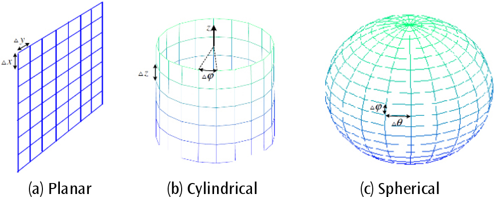
Cylindrical scans the antenna aperture on cylindrical contour. This is mainly useful for measuring fan-shaped beam patterns. Also, the spherical scans the antenna aperture on spherical contour. This advantage allows for the precise measurement of the patterns of very low-gain omni-antennas.
3.1.3. CPTR facility
The selection of a test range may take several aspects into account; including the technical and environmental, as well as the size of the antenna, the satellite, the frequency, the parameters to be measured and their accuracy, the measurement time, and so on.
Fig. 6 shows the configuration of the CPTR facility for creating a test zone. The rays from the feed located at the focus of the sub-reflector are radiated to the sub-reflector, and the reflected rays from the sub-reflector are illuminated to the main reflector. Then, the rays incident on the main reflector are reflected from the surface of the main reflector and collimated into high-quality plane waves as they reach the test zone. In the test zone, the antennas and the payloads with antenna can be precisely measured at the payload or system level.
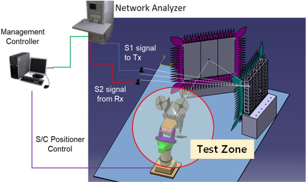
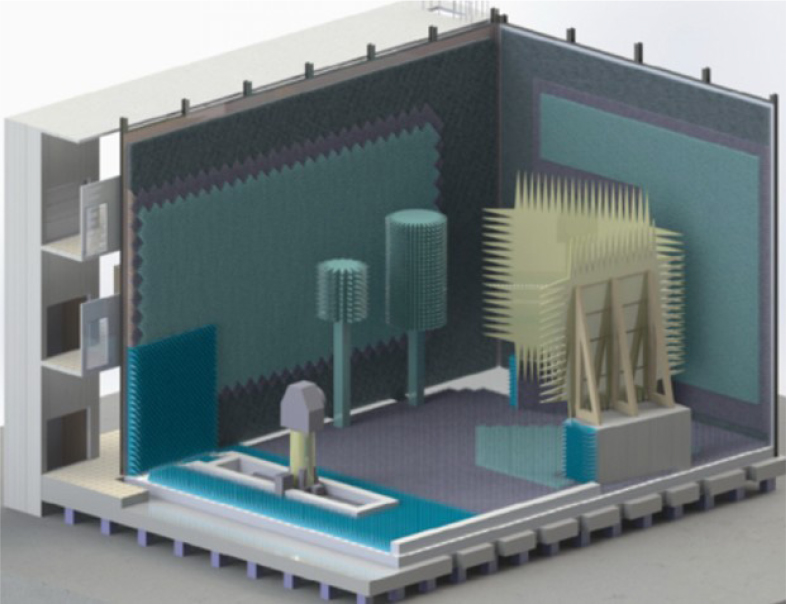
The CPTR facility provides a test space isolated from external environments such as external radios, vibrations, and temperature. In particular, it is intended to control external radios that may affect the in-door measurement environment, as well as to control the risks which may occur due to external leakage of high energy radiated from the antennas, payloads or satellite under test. Generally, the CPTR facility shown in Fig. 7 mainly consists of an anechoic chamber, collimator, RF instruments, and a positioner for the test specimens [3,4].
The anechoic chamber is mainly shielded with metal to isolate the electromagnetic waves between the inner and outer parts of the chamber in order to create an independent space which provides an appropriate measurement environment. Above all, in the case of electromagnetic shielding, electromagnetic waves can be blocked by the use of metal panels, but high energy generated may be reflected back into the test zone from the metal panels, which may significantly reduce the precision of the test or damage the test measurement system or the test specimens.
Therefore, by aligning radio absorbers to the floor, ceiling, and all walls, electromagnetic waves reflected from the metal panels are minimized into secure levels. The parameters that determine the quality of the test zone are composed of amplitude taper, amplitude (ripple), phase taper, phase ripple, and cross-polarization level, which can affect the actual measurement results.
The collimator for generating high-quality plane waves mainly uses a single-reflector or a dual-reflector illumination system. It converts the spherical wave radiated from the feeder into the plane wave in test zone. The size of the illumination system including the feeds plays an important role in the size of the test zone and the plane wave quality. Factors that determine the quality of the test zone are also very important, such as the reflector edge shape, serration, absorber aligning, precision machining, and precision alignment of the illumination system.
3.1.4. CPTR facility under development at KARI
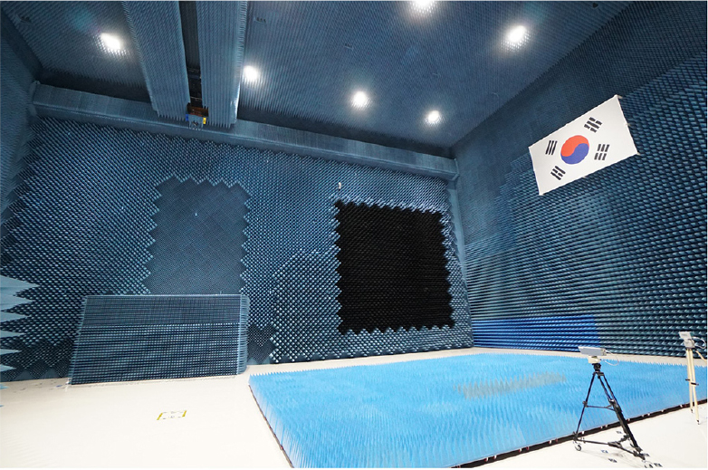
In 2017, the construction of a large electromagnetic chamber for electromagnetic compatibility verification of large satellites was completed at KARI as shown in Fig. 8. Since its construction, electromagnetic environment tests of large satellites such as geostationary satellites and earth observation satellites have been conducted in the LEMC chamber. The electromagnetic chamber measures 27.3 m long, 20 m wide and 16 m high, and was designed to reflect the infrastructure for the CPTR during the its construction phase. Seismic base was applied to isolate the effects of external vibrations during the test. In addition, foundation platforms were installed for the installation of reflectors for the implementation of the far field.
As shown in Fig. 9 the CPTR facility currently under development in LEMC consists of a dual-reflector system. Before launch, it will be performed for the End-to-End of the satellite payloads with antennas on the CPTR facility. It is used to characterize various payload or system level parameters, including the equivalent isotropically radiated power, saturation flux density, system noise temperature, group delay and the gain vs. frequency response. The main characteristics are as follows;
• Dual reflector system
• Support PNF scan and far-field measurement
• Test zone (QZ) size: Diameter 5 m × depth 6 m
• Frequency range: 1~50 GHz
• Positioner capacity: 5 ton (weight)
The measurement types of the test facility are as follows;
• Antenna measurements
• Characterization of payload parameters
• End-to-end testing
3.2. Analysis of Large Thermal Vacuum Test Facility
3.2.1. Status of Domestic and Overseas Facility
The largest thermal vacuum chamber currently available in Korea is the Large Thermal Vacuum Chamber (LTVC) at KARI completed in 2006 as shown in Fig. 10. The LTVC is a cylindrical chamber measuring 8 m in diameter and 10 m in length. It utilizes liquid nitrogen (LN2) to lower the internal temperature to as low as -185°C, and it is equipped with halogen lamps capable of generating high-temperature conditions inside the chamber. The chamber have 840 T-type thermocouple (TC) channels and 100 DC power supply units. In addition, a gaseous nitrogen-based Thermal Control Unit (TCU) enables localized thermal control of the satellite, with temperatures ranging from -150°C to 120°C. The basic specifications of the LTVC, including this feature, are summarized in Table 1. The LTVC is the only facility capable of performing orbit environmental testing for large satellites in domestic field.
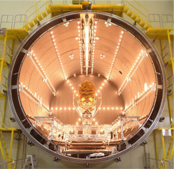
TABLE 1.
LTVC Specifications
Most major satellites developed domestically have undergone orbit environment testing in this chamber, such as the KOMPSAT (Arirang) series and the GK (Geostationary KOMPSAT) series. However, future satellite systems are expected to grow significantly and will require not only thermal and vacuum conditions but also the capability to simulate a wider range of space and planetary environments. For missions that demand high-precision data and long-duration operations, large-scale systems should offer greater stability and efficiency compared to the miniaturized alternatives. Accordingly, the development and verification of reliable, large-scale space systems require the establishment of an expanded space environmental test facility. Current facilities are not sufficient for larger satellites or space telescopes that may be developed in the future.
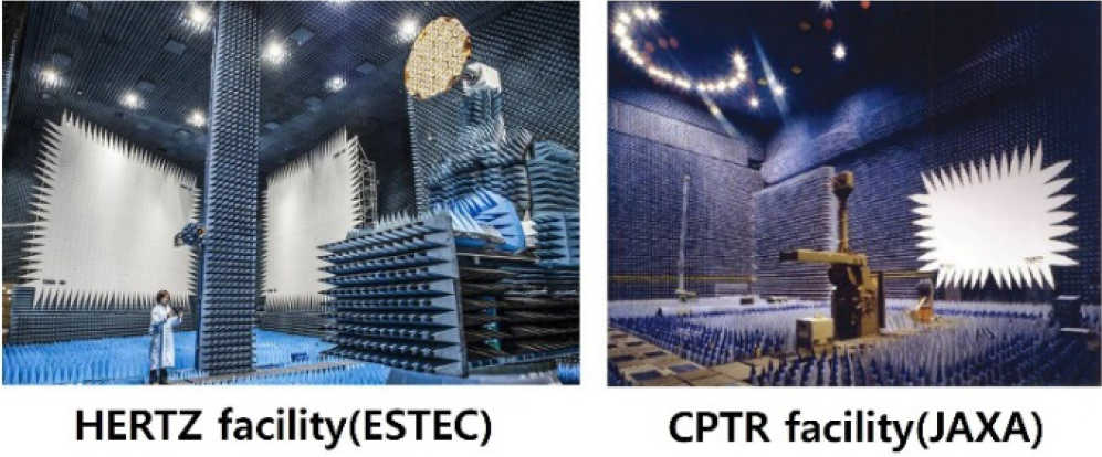
Globally, major space agencies operate large thermal vacuum test facilities. NASA’s Landsat-9 satellite underwent testing at NASA Goddard Space Flight Center (GSFC)’s large thermal vacuum chamber, while ESA’s Envisat satellite was tested using the large thermal vacuum chamber at ESA ESTEC. Additionally, NASA’s Hubble Space Telescope and James Webb Space Telescope (JWST) underwent testing at NASA GSFC and Johnson Space Center (JSC), respectively [5,6].
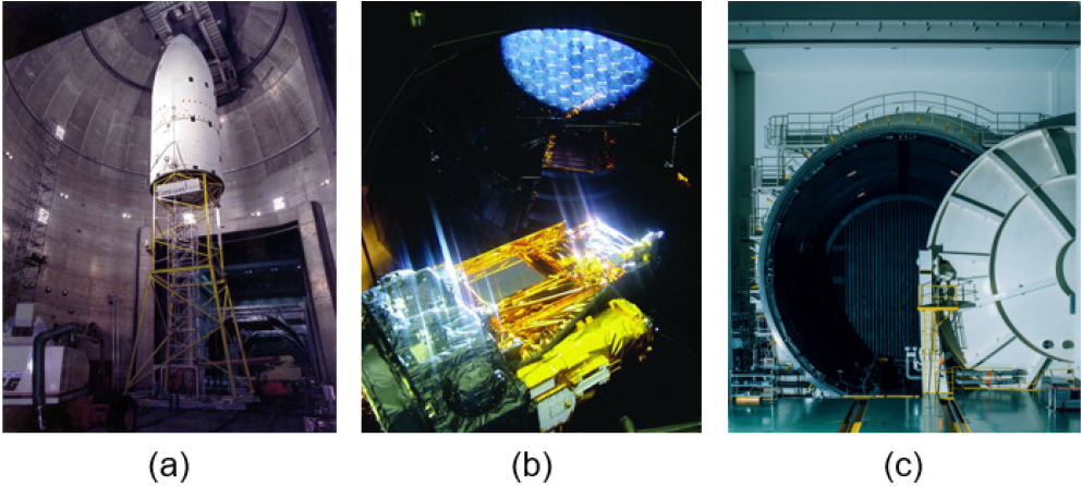
As shown in Fig. 11(a), NASA’s Space Power Facility (SPF) at the Glenn Research Center is the world’s largest thermal vacuum chamber, which has 30 m in diameter and 37 m in length, and is used for testing Mars probes such as Opportunity and Spirit, as well as the Orion manned spacecraft. ESA’s Large Space Simulator (LSS), measuring 15 m in diameter and 10m in length, is equipped with a solar simulator and a rotating platform, allowing for a more precise environmental testing. Japan’s JAXA Tsukuba Space Chamber, with a diameter of 13 m and a length of 16 m, is used for testing the Hayabusa2 and Akatsuki probes (Fig. 11(b), (c)).
All major space agencies possess thermal vacuum testing facilities larger in scale than KARI’s LTVC, and they have used these facilities to verify large satellites, space probes, space telescopes, and other similar missions. To verify high-precision, large-scale satellites for space security and to ensure the successful execution of their missions, a larger thermal vacuum testing facility is essential. Securing such a facility is also crucial for future space exploration and the growing competition over space resources.
3.2.2. Configurations for large thermal vacuum chamber
Determining the installation configuration of thermal vacuum chamber is a critical factor in the design and construction of facilities intended for orbit environmental testing of large satellites. Thermal vacuum chambers for space environment simulation are generally classified into two types based on their orientation: horizontal and vertical configurations. The configuration affects not only the procedures, time requirements, and complexity of satellite installation but also the reliability of the date acquired during thermal vacuum test.
As satellite platforms continue to increase in numbers, the optical payloads are also growing in aperture. Consequently, the chamber configuration must be carefully considered with respect to its influence on the optical system assembly, the alignment, and the metrology processes.
Currently, the majority of thermal vacuum chambers developed for medium- to large-class satellite testing have adopted a horizontal configuration.
The representative examples for them include LTVC in KARI, JAXA’s 13 m Space Chamber, and NASA’s Vacuum Facility-6, used for the electric propulsion system. Horizontal chambers offer significant advantages in terms of operational safety, as satellite integration is primarily conducted in the horizontal direction. This orientation reduces the need for complex safety preparations, thereby minimizing both time and cost. Furthermore, the horizontal layout improves accessibility for personnel and reduces the risk of accidents, resulting in enhanced overall work efficiency and safety.
However, as satellites become larger and heavier, the gravitational influence acting on the structure during horizontal installation become increasingly significant. In particular, for systems such as KOMPSAT-6 and -7, which have a high center of mass, the structural stability may be compromised in a horizontal orientation. Gravitational deflection and resulting deformations can induce wavefront errors in optical payloads, thereby reducing the repeatability and reliability of test measurements. Gravity compensation mechanisms are essential for large satellite systems in horizontally configured chambers. These auxiliary support structures, while necessary, introduce additional complexity and cost, and may reduce the overall efficiency of the test process.
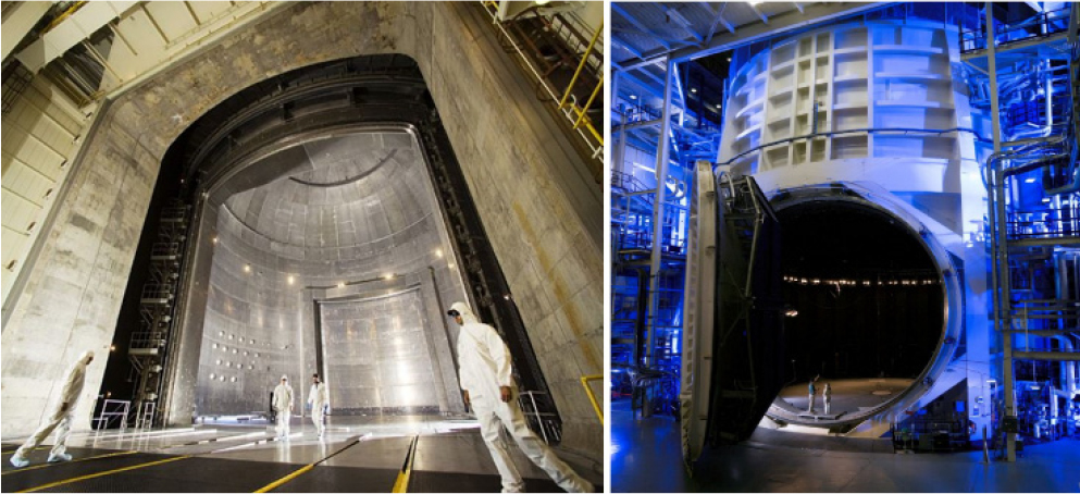
Many of the limitations observed in horizontally configured thermal vacuum chambers can be mitigated by adopting a vertical configuration. As a result, environment testing for numerous large-scale space systems has been conducted using vertically oriented thermal vacuum chamber. Notable examples include the NASA SPF which is the world’s largest thermal vacuum chamber with 30 m in diameter, Chamber A at NASA JSC as shown in Fig. 12. The LSS at ESA also has vertically oriented configuration.
In vertically configured chambers, satellites are typically installed in a vertical orientation, which significantly reduces the structural instability and deformation issues associated with horizontal setups. Furthermore, even as the satellite diameter increases, the integration and installation procedures generally remain unchanged, thereby allowing existing workflows to be reused without major modification.
This is particularly advantageous for large satellites equipped with primary mirrors exceeding 2 m in diameter, where minimizing wavefront errors is critical.
While auxiliary fixtures and gravity compensation devices can be utilized to address these challenges in horizontal configurations, the associated fabrication, operation, and labor costs are considerable. From a cost-efficiency and process simplicity perspective, the vertical configuration is generally more favorable for testing large satellite systems.
However, vertical chambers also present unique safety challenges that need to be carefully addressed throughout all stages of operation. As satellites are mounted in a vertical orientation, high-elevation work becomes unavoidable, necessitating the implementation of rigorous safety measures and procedures within limited spaces. Protection systems must be established to safeguard both personnel and hardware from falling objects, and the design and implementation of such systems often entail additional costs and schedule delays. Increased complexity in operational tasks ultimately extend the development timeline and raise total project costs, underscoring the need for thorough consideration of these factors during the planning phase. Based on the above discussion, the characteristics and comparisons of the two configurations are summarized in Table 2.
TABLE 2.
Comparison of Chamber Configurations
3.2.3. Considerations for Construction
To establish a new test facility capable of conducting thermal vacuum testing for large satellites, it is essential to consider not only the space required for installing a thermal vacuum chamber but also the additional space needed for auxiliary systems and equipment. While specific requirements can vary slightly depending on whether the chamber is installed vertically or horizontally, several key considerations remain fundamental across all designs.
One of the most critical aspects is ensuring that the facility provides ample internal space to support the full range of satellite-related operations, including transportation, integration, and installation. Given the expected scale of next-generation large satellite platforms, the chamber should ideally measure approximately 10 m in diameter and 20 m in length or height. For vertical installations, a minimum ceiling height of 30 m is necessary to enable satellite placement via overhead crane systems. In cases where building height is restricted, the use of underground space should be adopted, as has been effectively implemented by major international institutions such as NASA and DLR [7]. Beyond the space required for the chamber itself, at least 400 square meters of additional workspace should be allocated for hardware modification and handling. Furthermore, adequate provisions need to be made for receiving and unloading areas, air shower zones, storage rooms for components, checkout rooms, auxiliary laboratories, and office spaces for technical and operational personnel.
In addition to spatial planning, maintaining proper environmental conditions within the facility is of paramount importance. Satellite development and testing should take place in cleanroom environments due to the sensitivity of electronic components and the need to prevent surface contamination. All areas through which the satellite is moved, assembled, aligned, or tested should maintain a cleanliness level equivalent to ISO Class 8 (Class 100,000). Temperature and humidity should be regulated to 20 ± 2°C and 40-60% relative humidity, respectively.
However, when testing for optical or optoelectronic payloads, a more strict environmental control is required.
In such cases, a cleanliness level of ISO Class 5 (Class 100), with temperature held at 20 ± 0.5°C and humidity between 40-50 %, should be ensured to protect the precision and functionality of these sensitive systems.
Finally, given the structural and electronic complexity of large satellite systems, efforts need to be made to isolate the test environment from external vibrations. Vibrations and acoustic noise generated by support systems, such as HVAC units, cooling water circulation, and power supplies, can significantly impact test accuracy.
To address this, it is recommended that the support systems are installed in separate buildings, physically isolated from the thermal vacuum chamber. Furthermore, any unavoidable vibrations should be mitigated through the use of a dedicated seismic mass (e.g., a reinforced concrete block) installed under the chamber. This structural decoupling minimizes the transmission of vibrations into the test chamber and helps maintain the integrity of the test environment [8]. Table 3 summarizes the design considerations and requirements for the construction of the new thermal vacuum test facility.
TABLE 3.
Requirements of Chamber Construction
3.3. Analysis of Vibration and Static Load Test Facility
3.3.1. Overview of Satellite Launch Environmental Testing and Test Requirements
During the launch, a satellite is subjected to extreme vibration, acoustic, and shock loads from the launch vehicle used to launch the satellite to its target orbit for achieving its mission. To verify that the satellite will function normally in the launch environment, the tests are conducted on the ground. Launch environment tests include vibration test, acoustic test, and separation shock test. And vibration tests are categorized into dynamic test and quasi-static load test.
Dynamic tests for satellites include random vibration test and sinusoidal vibration test. The sinusoidal vibration test uses a sinusoidal signal in the band 5-100 Hz with sweep rate of 2 to 4 octave/minute, and the satellite is accelerated to about 1 g. Random vibration tests using a shaker are mainly performed on small satellites in the frequency band 20-2000 Hz, while larger satellites are subjected to random vibration tests using acoustic test chamber.
During the final stage of engine burn, when the mass of the launch vehicle is at a minimum, the acceleration due to rocket propulsion is at the maximum point and the satellite is subjected to a maximum static load. Loads ranging from 4 to 10 times the weight of the satellite are applied to the satellite. In the case of satellites, static load test is not practical and is verified by means of quasi-static load test with a sinusoidal signal applied several times at frequencies below one-third of the satellite’s first natural frequency.
Vibration test for satellites are typically performed by an electrodynamic shaker system or hydraulic shaker system. Electrodynamic shaker control the current through a cylindrical armature coil and generate an electromagnetic force between the field coil and armature coil, which can be over a wide frequency band from 5 to 2000 Hz. This makes dynamic load testing of satellites, including random and sinusoidal tests. Korea Aerospace Research Institute (KARI) has LDS’s V964, V984, and V994 shakers. And in 2017, it built new large-scale vibration test facilities, which were composed of horizontal vibration test system(HVTS) and QUAD vertical vibration test system (QVTS) shown in Fig. 13[9]. Key performance specifications of the system are shown in Table 4. However, electrodynamic shakers have a small stroke and cannot make high levels of acceleration in the low frequency band below 10 Hz. In particular, large satellites developed recently have a large mass and a low first natural frequency, which also lowers the test frequency of quasi-static load tests, making it difficult to perform the tests on large satellites with electrodynamic shakers.
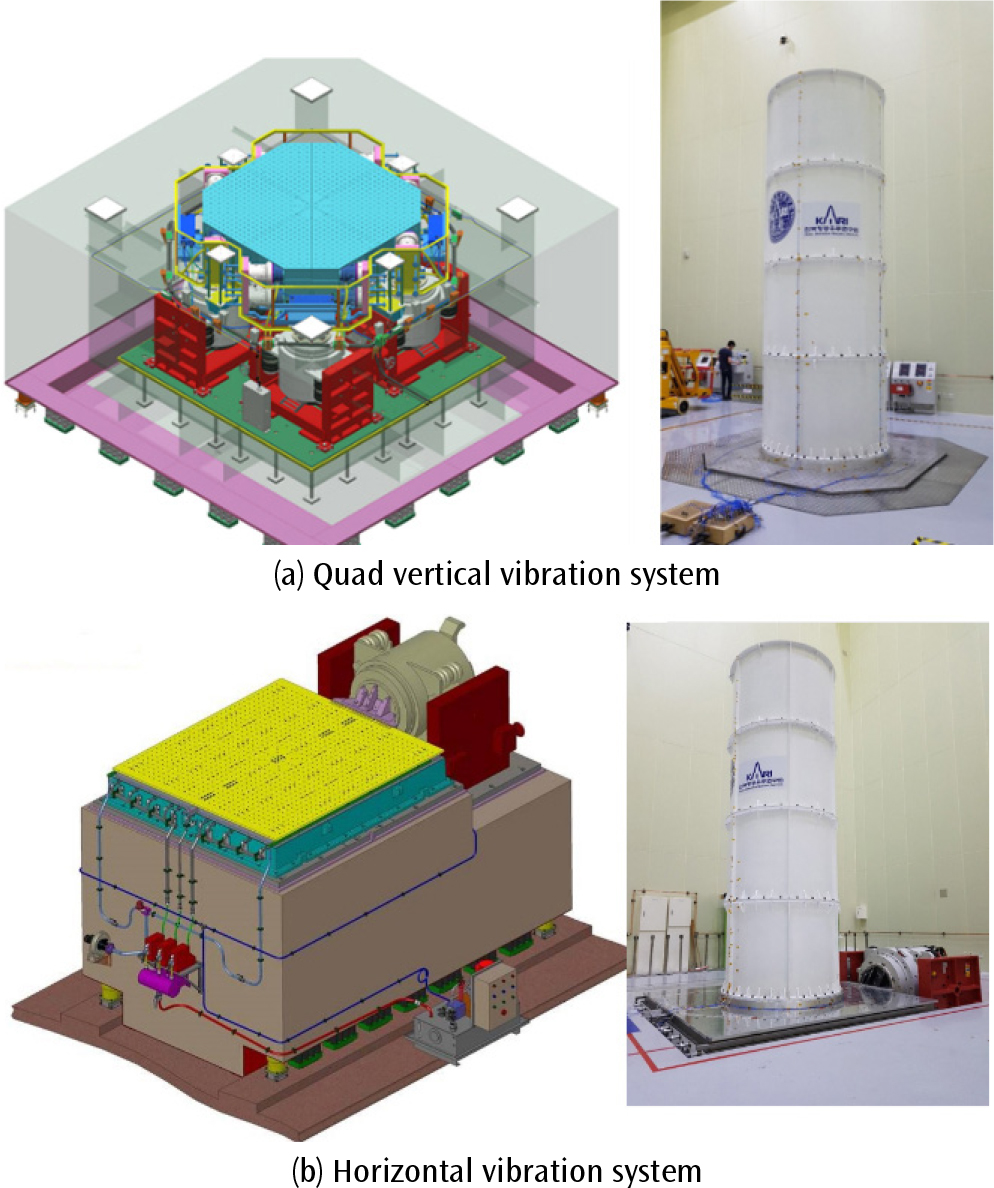
TABLE 4.
Specification of large vibration test facility at KARI
| Item | Vertical shaker | Horizontal shaker |
|
Test Mass (with Fixture) | 10,000 kg | 10,000 kg |
| Interface Diameter | 3.25 m | 3.25 m |
| Excitation force | 640 kN | 280 kN |
| Moment capacity | 300 kNm | 1,000 kNm |
Hydraulic shaker system typically utilizes electro-hydraulic servo value, a method of electrically controlling the movement of a hydraulically actuated actuator by intervening servo valves.
By regulating the flow rate of incompressible fluid inside a hydraulic cylinder, very strong forces and high accelerations of more than 500 kN in the low frequency band below 100 Hz can be generated, and to perform long stroke tests with p-p displacements of more than 200 mm. However, hydraulic system is only capable of low-frequency vibration test, so they are more suitable for quasi-static load tests in satellite launch environment tests.
In relation to the establishment of a space environment test facility for large satellites, this project investigated the hydraulic system for launch environment tests, planning to be utilized for quasi-static load tests of large satellites in the future. Accordingly, the quasi-static load test requirements for two types of hypothetical satellites were set as shown in Table 5. and the quasi-static vibration tests of these satellites were investigated.
TABLE 5.
Test Requirements of Satellites
3.3.2. Analysis of domestic and international facilities for static load test
1) HYDRA at ESTEC
The Hydraulic Multi-axes Shaker (HYDRA) at the European Space Research and Technology Center (ESTEC) in Noordwijk, the Netherlands, is a hydraulic shaker capable of simultaneous accelerations in all axes (translational, rotational) in the range of 20 mg-3 g over the frequency band 1-100 Hz [10]. Installed in 1996 and modified in 2011, HYDRA has been used to perform vibration tests on several satellites, including Envisat (the largest civilian Earth observation satellite ever built at 8 tons), Herschel, and a 22-ton ATV filled with propellant tanks, as shown in Fig. 14.
HYDRA’s key performance specification is shown in Table 6. With 5 meter interface , a maximum height of 12 meters, and a mass of up to 22.5 tons, and is capable of testing satellites with a maximum displacement of 70 mm and a maximum velocity of 0.8 m/s with a force of up to 630 kN. However, HYDRA does not meet the requirements in Table 5 for maximum acceleration (7 g for large satellites and 8 g for medium satellites). Furthermore, since the equipment is owned by ESA in the Netherlands, it does not meet the objectives of this task from a security perspective, as it would result in the leakage of domestic space technology and high test costs.
TABLE 6.
Specification of HYDRA at ESA ESTEC
2) TABLE S Hydraulic System at Pusan National University Seismic Simulation Test Center
Hydraulic facilities in Korea that can be utilized for large satellites and launch vehicles were investigated. Each new facility would cost more than 10 billion won to build. However, environment test of structural models does not require a clean room, and it is possible to build a separate air conditioning facility.
TABLE S of Pusan National University Seismic Simulation Test Center in Fig. 15 is a hydraulic vibration system made by MTS, which can control vibration with 6 degrees of freedom [11]. When the modes of rolling and yawing in the unidirectional direction appear, the vibration system can control the cross axis response by applying a counter load to zero it. In addition to controlling the cross axis motion, the TABLE S vibration Table can also measure and control the rebound caused by the sample behavior in real time for normalization of the input load.
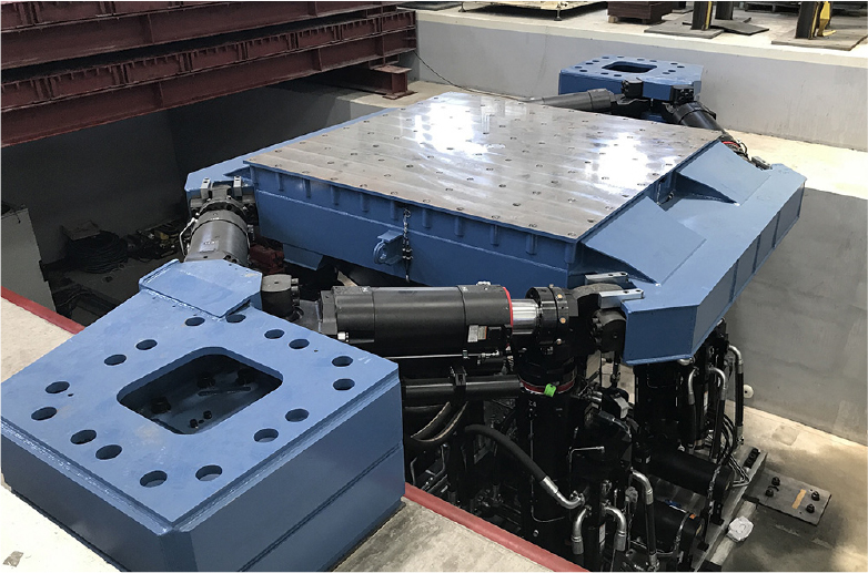
TABLE S’s key performance specification is shown in Table 7. The maximum size of the surface where the satellite will be installed is 2.5 meters by 2.5 meters, the p-p amplitude horizontal axis can be up to 250 mm and the vertical axis can be up to 150 mm, and the maximum payload can be tested up to 6 tons. The quasi-static tests in the vertical and horizontal directions of these satellites can be realized using the TABLE S system. The constraints of the TABLE size of 2.5 m × 2.5 m in TABLE S are expected to be solved by designing an appropriate fixture, and it is expected that quasi-static testing of the large scale satellite will be possible.
TABLE 7.
Specification of TABLE S
However, the laboratory of the Pusan National University Seismic Simulation Test Center is currently not air-conditioned, so it is not possible to perform the test for Flight Model of satellites, but Structure models can be tested.
Currently, Pusan National University Test Center is conducting various industry-academic research projects with various industrial companies and academic institutions related to hydraulic vibration testing. In the future, it is expected that quasi-static tests can be performed on SM of large scale satellites.
3.4. General requirement of assembly and test room facility
The main considerations for the design of assembly and test rooms are the floor load, height of the test room, door size, crane capacity, crane speed, and air conditioning requirements. For assembly rooms for large satellites, the design of the test room floor load is important. It should reflect the load conditions caused by the operation of multi-purpose trolleys for the assembly of large satellites and the load conditions applied to the room floor during the installation and transportation of satellites in satellite shipping containers. Especially in the unloading room, assembly room, and the air-lock area, the building floor must be designed with enhanced distributed and concentrated loads. Table 8 is a minimum specification that can be applied during the test hall design phase, and additional operating conditions must be considered during the actual test facility construction phase. In addition, the unloading room and air-lock should be configured in such a way that there is no underground space under the unloading room and air-lock, so that the satellite transportation vehicle can be brought in and out without any problems.
TABLE 8.
Floor loading case
| Floor loading condition | Value |
| Floor load | 20 kN/m2 |
| Point load on a grid 1.5 m × 2 m | 50 kN |
| Block load on area 2.5 m × 2.5m | 250 kN |
The crane capacity should be designed to be 10 tons for the operation of the proposed large satellite, and the unloading room should be equipped with a crane of at least 20 tons for the operation of the shipping container. Due to the very frequent use of the crane during the assembly and installation of the satellite, the control of the crane should be designed to allow fine speed adjustments. An additional inverter control circuit should be applied to provide a precise control of the crane by categorizing it into low and high speed modes. Table 9 shows the travel speed requirements of the crane for the test facility. The crane shall be designed to provide a minimum height of 15 m for operation. The door for the satellite passage in the test hall should be designed with a height of 10 m and a width of 7 m for the maximum movement of the test object. Based on international practice, the door of the unloading room should be designed with a height of 12 meters and a width of 8 m. The operating environment should be designed with HEPA filter and air conditioning system to a cleanliness class of 10,000, temperature 21 ± 3°C, humidity 55% ± 10%.
4. SECURITY MANAGEMENT STRATEGY
4.1. Organization of a test center for public-private partnership testing
Public-private partnerships require physical security to ensure that satellites are not exposed during assembly and testing. When multiple satellites are brought into the test center to perform various environmental tests, the movement of each satellite must be controlled so that it is not exposed to the development personnel of other satellites. For this purpose, it is important that various test facilities and assembly rooms are arranged in such a way that physical security is secured during the construction of the test center. To this end, we first conducted a survey and analysis of the current configuration of major overseas test centers. JAXA in Japan, ESTEC in Europe, and IABG, a leading German test center, were analyzed for the configuration of space environment test facilities. Based on the analysis results and the operating experience of KARI SSETC, we proposed the configuration of the test center as shown in Fig. 16(a).
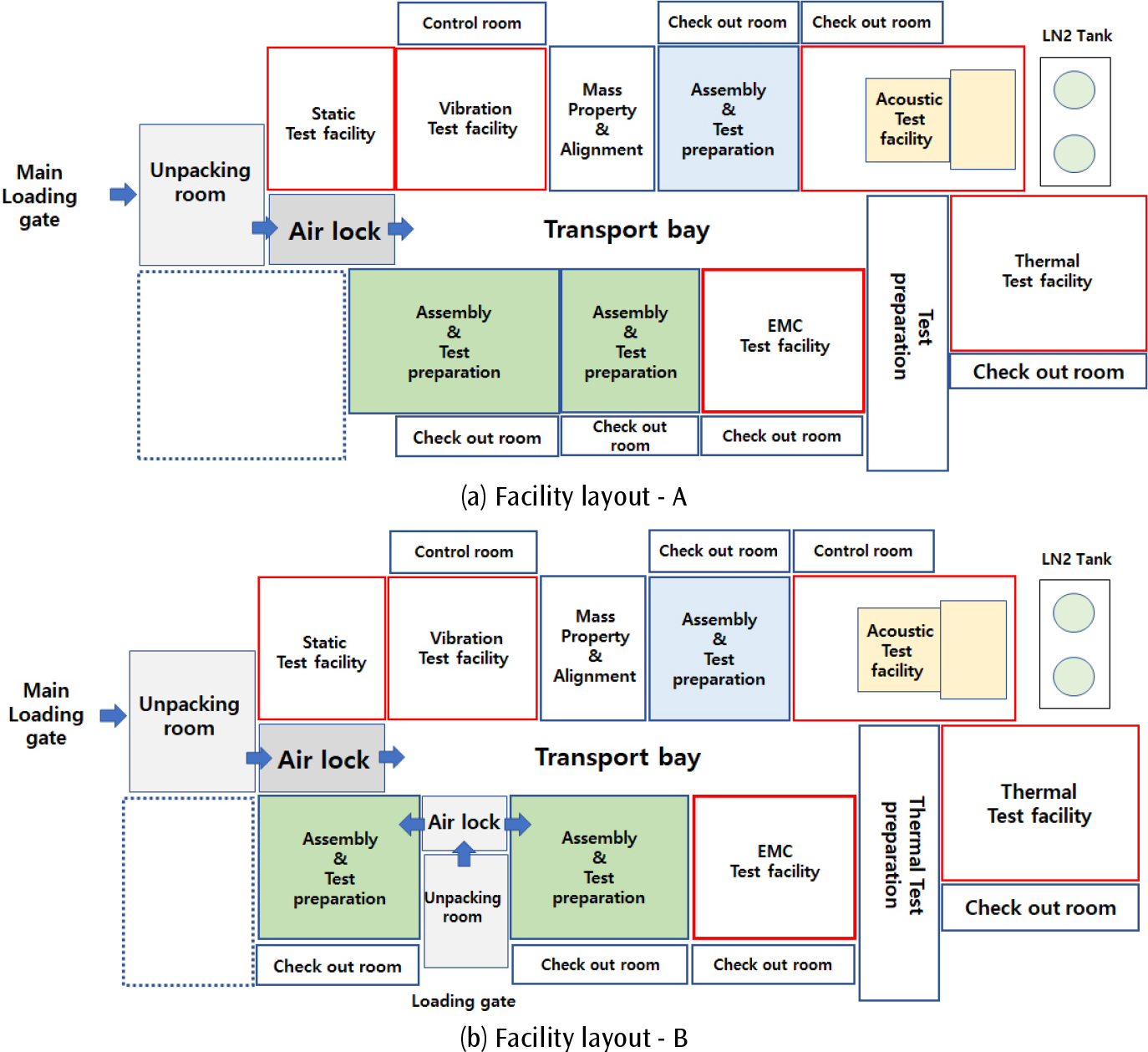
The unloading room for the loading and unloading of satellites connected to the main loading gate was placed first. Since the unloading room is where the satellite containers are brought in and various preparations for transportation to the launch site are performed, a relatively large space is advantageous for performing related tasks. An air lock was placed between the inside of the center and the unloading room to ensure the hygienic state within the center. Static test facilities and vibration test facilities are located adjacent to each other so that the launch environment tests can be performed. The thermal test facility, which requires a relatively large amount of space during the test preparation process, was located at the right end, and the acoustic chamber was placed next to the thermal test facility for joint use of the LN2 tank. In the assembly room and the main test room, a check out room was placed to perform satellite control and related tests. The plan in Fig. 16(b) shows an additional unloading room. This has the benefit of controlling the security of the satellites in and out of the test facility.
4.2. Space Environment Test Facility Security Management: Concepts, Regulations, and International Case Studies
This chapter examines the concepts and regulations related to security management in the space environment and satellite test facilities, and analyzes international case studies. Security management in space environment test facilities refers to a systematic management approach aimed at protecting facilities and information assets through physical security, cybersecurity, and personnel security measures during satellite testing and evaluation. The primary objectives are to prevent satellite technology leakage, maintain data integrity during testing, and ensure the safety of facilities. Given that these facilities accumulate highly valuable technical data and sensitive information, establishing a robust security management system is essential.
Reflecting this importance, international standards and governmental organizations specify regulations related to security for satellite test facilities. Notably, NASA in the United States established rigid security management standards for satellite test facilities through the NASA Security Program Procedural Requirements (NPR) [12]. The NPR provides comprehensive guidelines addressing various aspects such as facility access control, personnel identification and authentication, cyber-security requirements, incident response procedures, and information protection protocols. It mandates strict adherence to security procedures to safeguard critical infrastructure and sensitive technologies from unauthorized access or damage. The European Space Agency (ESA) provides standards for protecting information and facilities related to satellite testing through ESA Security Directives [13]. These directives outline mandatory security protocols, including the management of classified information, physical protection of facilities, security training requirements for staff, and the stringent control of access to sensitive areas. ESA Security Directives emphasize maintaining confidentiality, integrity, and availability of critical data and ensuring continuous compliance through regular audits and inspections. When multiple customers utilize ESA facilities simultaneously, strict partitioning of work areas and access rights ensures confidentiality between competing missions.
In terms of international case studies, NASA maintains strict physical security through facility access control systems, real-time monitoring, and intrusion detection systems. Additionally, NASA operates comprehensive cybersecurity practices such as test data encryption, network segmentation and redundancy, and regular training programs for internal staff [13]. Similarly, ESA emphasizes personnel security by routinely conducting security education programs and strictly controlling facility access [10].SpaceX explicitly defines physical security measures to ensure safety in Falcon launch vehicle operations. All facility entry doors are strictly controlled via locking mechanisms, and launch site badges are required for personnel entry, enhancing personnel security. Moreover, comprehensive video monitoring systems operate throughout facilities for constant surveillance and immediate security response [14]. In cases involving multiple customers, SpaceX implements clear physical partitions and designated secure spaces to ensure customers’ proprietary technologies and sensitive data remain segregated and protected. SpaceX further specifies security measures at the Vandenberg Space Force Base (VSFB), emphasizing controlled access through a strict badge approval process managed by SpaceX, especially for non-U.S. persons requiring escort arrangements. Additionally, specific facility areas at VSFB, such as processing bays and control rooms, are separated by security partitions or are designated to secure areas to accommodate multiple customers simultaneously. For instance, Bay 1 in the Payload Processing Facility (PPF) is separated from other areas by a 13-foot high security partition, ensuring strict confidentiality and protection of proprietary customer technologies. Shared spaces, such as gowning rooms, conference rooms, and common amenities, maintain badge-controlled access to enhance overall personnel security and restrict unauthorized access [14].
Arianespace, in collaboration with the French government and the Guiana Space Centre (CSG), maintains rigorous international-level security standards applicable to all launch systems including Ariane, Soyuz, and Vega launch vehicles. Facility access is strictly restricted, with security personnel providing continuous surveillance at road entrances and escort services for satellite transportation. Satellite access is strictly controlled via electronic card systems allowing only authorized personnel access to spacecraft preparation facilities. Additionally, clean rooms are monitored continuously by CCTV systems with recording capabilities to rigorously protect facilities and information [15].
Collectively, these cases illustrate that security at space environment test facilities requires integrated efforts across physical, cyber, and personnel security domains. NASA and ESA employ government-led structured security standards emphasizing the prevention of technological leakage, while commercial entities like SpaceX and Arianespace maintain comparable security frameworks to sustain their commercial competitiveness. These international cases provide important insights for establishing security management frameworks to advance the domestic space industry. Key strategies for strengthening domestic test facility security include standardizing the security criteria through public-private partnerships, introducing advanced technologies, and implementing continuous personnel training programs.
5. CONCLUSION
Large satellites are often developed for nationally important security information, such as high-resolution observation and communication satellites, and hence security is crucial for the development process itself . Therefore, it is appropriate in terms of security management to conduct assembly and ground verification tests in Korea during the development stage. To this end, the geometry and requirements of large satellites to be developed in the future were reviewed to derive design specifications for additional facilities and construction.
Building and maintaining a large space environment test facility requires a large budget. As shown in overseas cases, it is essential to increase the utility by jointly utilizing them for various projects of private companies and governments. In order to achieve the conflicting goals of joint utilization and security management, this study reviews and summarizes overseas security management practices and regulations. In addition, a layout of a test room for security management in the process of building a new environmental test facility is presented.
