

1. INTRODUCTION
2. CUBESAT DEVELOPMENT TREND
2.1. Global Trend
2.2. Domestic Trend
3. CUBESAT TECHNOLOGY FOR SPACE NATIONAL SECURITY
3.1. Earth Observation (EO/SAR)
3.2. RF Communication
3.3. Laser Communication
3.4. Summary of Technologies for Space National Security CubeSat
4. SUGGESTION FOR NATIONAL SPACE SECURITY CUBESAT SYSTEM
4.1. Analysis of Characteristics of Small Satellites Constellation System
4.2. Concept of Earth Observing CubeSat System
4.3. Concept of Communication CubeSat Constellation
4.4. Security System of Communication between CubeSats and Ground Station
4.5. Complementary Utilization of Small Satellites and CubeSats
5. PERFORMANCE ANALYSIS OF EARTH OBSERVING PAYLOAD
5.1. SAR and Hyper-spectral Sensor
5.2. Concept and Verification Research of Deployable Optical CubeSat in KAIST
5.3. Development Status of Laser Communication Module for CubeSat in KAIST
6. CONCLUSION
1. INTRODUCTION
CubeSat is small and economical satellite defined as 1 Unit (1U) in a 10 × 10 × 10 cm cubic frame [1]. CubeSats are commonly developed and launched by universities, research institutes, and corporations for various purposes such as test of technology, education, and research. CubeSats comprise individual modules with various subsystems like power, communication, observation, and control systems, and are typically designed and manufactured in 3U and 6U platform sizes. Most CubeSat missions are performed in Low Earth Orbit (LEO). But since a propulsion system is commonly not mounted on the CubeSat platform, the altitude decreases over time due to atmospheric drag, leading to a relatively short mission lifetime. However, they benefit from low launch costs and short production periods, allowing for rapid performance improvement and relaunch for continuous missions.
CubeSat projects are being progressed by many nations and organizations due to their shorter production times and lower costs compared to traditional satellites. CubeSats are initially developed only for educational purpose, their utility and practical applicability for space mission have been recognized over time, leading to their applications in a wide range of space missions, including Earth observation, weather and environmental monitoring, space component and sensor testing, and new space technology development.
CubeSats are also actively used in national defense and security. CubeSat is suitable to form a constellation in that they have tiny size, low cost, and require relatively less effort to replacing failed platforms. So, CubeSat is considered applicable to space national security in various ways.
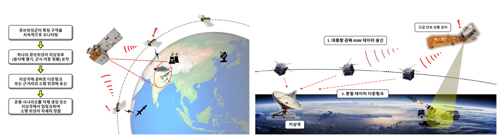
First, setting target areas for surveillance, CubeSat constellation can be deployed with appropriately designed orbit for continuous revisit and imaging. Images transmitted by the CubeSat constellation can detect military actions and threats to national security. Second, in military zones, normal communication can be challenging due to signal jamming. CubeSat constellation can be deployed to frequently visit military areas and augment military communication systems as part of the network. They can also provide temporary communication services in areas with poor communication quality.
CubeSats can also serve as low cost platforms for testing new technologies or systems that operate in extreme conditions (temperature, pressure, radiation, velocity, and microgravity, etc.) or from hundreds of kilometers away [2]. Their short design, production, and launch periods allow rapid deployment and iteration of testing new technologies. This enables quick response to market trends, creating new opportunities and energizing the domestic CubeSat market.
However, CubeSats have limitations compared to conventional satellites due to constraints in size and budget. They cannot mount large optical payloads and antennas required for high resolution images, complex experiments, and long-range communication. Also, the lack of propulsion systems leads to a shorter mission lifespan, necessitating continuous performance improvement and relaunch. For the application of CubeSats in space national security, it is necessary to clearly understand the strengths and limitations of CubeSat platforms and research ways to maximize their advantages.
The results of this research will serve as a blueprint for future CubeSat missions and satellite system development for space security. Specifically, contributions are expected in wide area of space security. First, Multiple CubeSats equipped with high resolution optics and sensors can be deployed in orbit for continuous surveillance of target area. Images captured by CubeSats will be used to monitor and analyze enemy movements and military facilities, providing critical information for monitoring international conflict zones, strategic points, and potential threats. Second, CubeSats can be used to augment military communication networks. Operating CubeSat constellation equipped with network equipment in LEO can prevent sensitive data theft during military communication, and communication with remote areas.
For broader meaning of national security, images captured by CubeSats in visible and infrared range can be used for real-time detection of and response to disasters such as fires, floods, volcanoes, and earthquakes [3]. Also, analyzation of accumulated data from CubeSats’ image can predict potential threats to national security by monitoring environmental changes. For instance, monitoring environmental factors threatening water resources, sea-level rise induced by climate change, and desertification, etc. CubeSats can also function as a part of space environmental monitoring systems, detecting solar wind and other space events. Lastly, considering that CubeSat is originally developed for educational purposes, actively utilizing them in space security, as proposed in this study, is expected to establish a foundation for training professional manpower in the space field through industry-university-institute collaboration.
2. CUBESAT DEVELOPMENT TREND
2.1. Global Trend
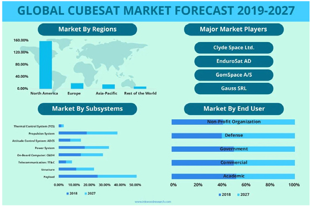
The global CubeSat market is rapidly growing for three decades, as briefly described in Fig. 1, which is a forecast report written by Inkwood research. According to market research firm Straits Research, the global CubeSat market reached USD 210 million in 2022 and is expected to grow at a Compound Annual Growth Rate (CAGR) of 15.1%, reaching USD 857 million by 2030. Another market research firm, IMARC Group, projected that the global CubeSat market, valued at USD 354 million in 2023, is anticipated to grow at a CAGR of 16.9%, reaching USD 1509 million by 2032. The rapid growth of the CubeSat market can be attributed to the expandability of CubeSat from their initial purpose, student education, to various field including research, space development, and surface imaging services. Additionally, due to the limited size and capability of CubeSat platform, CubeSat is primarily developed for LEO operation, often designed to form constellation. This has led to an increase in the number of companies which provide launch services capable of carrying numerous CubeSats to LEO or which connect customers (or, CubeSat developers) with launch providers.
The CubeSat market is expanding beyond the realms of educational purpose and research, moving into areas that support several industries and daily life. Expanded roles of CubeSat include identifying boundaries between river and land, analyzing the status of crops from visible light images and relaying this information to customers, augmenting internet networks, monitoring natural disasters through infrared imaging, and serving as testing platforms of electronic devices. CubeSat Companies are also classified according to their specializations. For example, in the CubeSat development part, companies offer various services such as development and testing of sensor and onboard computer, platforms for testing components in extreme environment (temperature, pressure, and radiation), communication services (including ground station antennas), CubeSat deployer, software, and CubeSat product online outlets. Additionally, Launch Providers don’t just mean the provision of launch vehicles. But they include the manufacturing and transportation of launch vehicles, planning and management of launch missions, and brokering between CubeSat developer and launch vehicle providers.
2.1.1. Dove Constellation (Planet Labs)
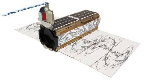
One of the most prominent areas of CubeSat application in space national security is optical imaging for surveillance and reconnaissance. For example, American company Planet Labs operates constellation of 3U CubeSat Dove [4], which is 5 kg and equipped with optical camera of 90 cm diameter (Fig. 2). Earth observation data acquired by Dove are released for various purposes to generate revenue. In particular, Dove demonstrated the potential and appropriateness of CubeSat application to the space national security for surveillance and reconnaissance during the Russia-Ukraine War that broke out in 2022, by capturing images of strategic locations such as the air force base near Kharkiv.
2.2.2. OCSD Mission (The Aerospace Corporation)
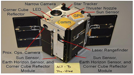
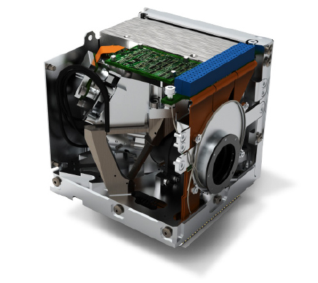
The OCSD project is a CubeSat mission developed as part of AeroCube program from The Aerospace Corporation, which is an unofficial U.S. Air Force agency [5]. This project aims to validate CubeSat technologies such as laser communication system and high precision attitude control. The OCSD mission operates with three 1.5U CubeSats equipped with advanced communication system and compact propulsion system (Fig. 3). The primary payload of the OCSD CubeSat, laser communication module, is considered a key technology for the future inter-spacecraft communication. These CubeSats were launched in December 2017 and demonstrated 100 Mbps space laser communication.
2.2. Domestic Trend
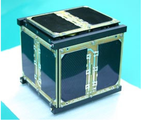
The first CubeSat of South Korea, HAUSAT-1 (Fig. 4), was launched in July 2006. Created by graduate students of Korea Aerospace University, this 1U CubeSat failed to enter orbit due to launch vehicle issue but provided students with a range of experiences in satellite design, manufacturing, performance testing, launch, and operation.
To provide graduate students and industries with opportunities to directly manufacture CubeSat and to mature national space technology, the Ministry of Science and ICT and the Korea Aerospace Research Institute (KARI) have been hosting a CubeSat competition (Fig. 5). Starting with the first competition in 2012, the 5th event was held in 2022. The CubeSats selected in each CubeSat competition are shown in Table 1.
TABLE 1.
CubeSats selected in each competition
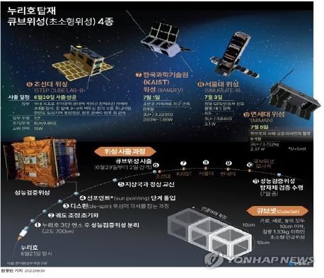
Unfortunately, none of these CubeSats achieved complete mission success. In the 2019 CubeSat competition, four CubeSats were selected to be launched on Nuri, the first domestic launch vehicle, in 2022 (Fig. 6). All missions successfully conducted bidirectional communication with ground station, but still none of them completed their missions without any issues in communication or attitude control.
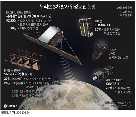
In May 2022, Hancom InSpace launched Sejong 1, the first domestic commercial CubeSat-sized satellite. The third launch of Nuri in May 2023 included eight CubeSats developed by research institutions and companies (Fig. 7). And signals from CubeSats by KAIROS Space and Lumir are confirmed by ground station. The SNIPE constellation of CubeSats developed by the Korea Astronomy and Space Science Institute (KASI) successfully received signals from three of four satellites.
As the international CubeSat market grows, there is an increase of startups in Korea as well providing CubeSat design, component manufacturing, and environment test support. Since 2021, the Ministry of Science and ICT has been implementing the Space Pioneer project for ten years, aiming to secure core technologies, enhance the capabilities of domestic space technology, and establish a virtuous cycle in the space industry. The goal is to develop 16 core space technologies through industry-academic-institute consortium.
2.2.1. Problems and Solutions in the Domestic CubeSat Industry
This study presents the problems and limitations currently facing the South Korean CubeSat industry and market, and also proposes possible solutions to resolve these issues and vitalize the domestic CubeSat market and development of the core technologies.
First, due to the insufficiently matured technology and manufacturing capabilities of satellite components, most of the current domestic CubeSat projects import core components such as attitude determination sensors and communication antennas from foreign companies.
Second, the geographical condition of South Korea is not favorable for radio communication between ground station and satellites in LEO. Due to the insufficient length in both north-south and east-west directions, mission opereators should wait for the revisit cycle of the CubeSats for transmitting commands and receiving mission data rather than geostationary orbit (GEO). For example, it took several months to carry out a code patch using only one domestic ground station for the MIMAN CubeSat, which was launched in 2022. A short-term solution to address this issue is to construct or to rent ground station in the polar region to increase contact time.
Furthermore, the roles of government-contributed research institute and universities in the domestic CubeSat market are not clear in these days, leading to a lack of smooth cooperation between them. So, it is necessary to institutionally establish a definition for role distribution and complementary cooperation among government-contributed research institutes, universities, and companies to energize the domestic CubeSat industry and market.
Lastly, an institutional mechanism should be established to introduce and settle a virtuous cycle structure in CubeSat technology development, starting with the presentation of innovative new technologies, followed by orbital verification and evaluation.
3. CUBESAT TECHNOLOGY FOR SPACE NATIONAL SECURITY
3.1. Earth Observation (EO/SAR)
3.1.1. Electro-optics (EO)
EO device converts light intensity into electrical signal, encompassing most digital optical sensors. In the context of satellite payloads, EO primarily means the camera that captures the visible light range. For general satellites, EO payloads equipped to operate in LEO can achieve resolution below 1 meter and swath width of over 10 km.
A notable example of EO payload mounted on CubeSat for Earth observation mission is Dove constellation, developed and operated by Planet Labs. Dove is 3U CubeSat and weigh approximately 6 kg. Both Dove-1 and Dove-2 mount the same image sensors and EO payloads with an aperture of 90 mm. Dove-1 orbited at an altitude of 250 km, while Dove-2 covered an orbit of 300 × 575 km, and both achieved a resolution of 4.4 m.
Compared to conventional visible light optical systems for satellites, EO payload for CubeSat face distinct performance limitations due to the volume constraint of the CubeSat platform. For instance, light-gathering power, which determines resolution and SNR, is directly proportional to the aperture diameter. However, because of the volume limitation of CubeSat platform, EO payload of CubeSat could not secure sufficient light-gathering capacity. Typically, an exposure time of less than 1ms is set for capturing a single image in LEO considering orbital velocity, but for CubeSat EO payload it is not enough time to utilize the full photon depth of image sensor. Consequently, it is necessary to develop imaging techniques to slow relative ground speed and compensate for ground track displacement due to Earth’s rotation.
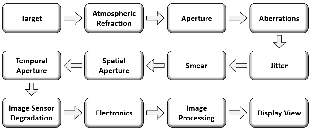
Moreover, in general CubeSat does not have sufficient capability of attitude control to withstand disturbance which affects Spatial Detail of image. As illustrated in Fig. 8, various factors degrade the Modulation Transfer Function (MTF) of EO payloads, but CubeSat platform struggles to effectively control these factors, resulting in MTF losses. The principal limitation of CubeSat EO payload is the diffraction limit. Though diffraction limit is reduced by increasing the aperture of EO, CubeSat platform has inherent constraint on the diameter and volume of payloads, so there is ceiling of resolution.
Additionally, the operational frequency of imaging and processing is inherently limited considering power and thermal management considerations. Frequent activation of the EO can generate significant local heat, jeopardizing the CubeSat’s thermal stability, hence the need for thermal environment simulations and design of optical systems considering thermal cycle (e.g., Thermal Gradient). Lastly, since most of CubeSat missions are operating in LEO, revisit cycle is longer than other orbits, and the downlink speed is restricted by diameter of antenna and power schedule. Transmitting 1Tbit of RAW images at X-band 100 Mbps would take about 3 hours. However, CubeSats orbiting below 500 km altitude pass over a ground station only 2-3 times a day, with limited link duration (mostly 15 minutes), resulting in significant time spent on downloading images. Proposing onboard computer image processing and downlink compression as a solution, image processing consumes substantial power and generates considerable heat, thus limiting Duty Cycle.
3.1.2. Synthetic Aperture Radar (SAR)
SAR is a technology capable of creating topographic maps and observing the surface by processing the time difference when radar fired towards the Earth’s terrain, including land and oceans, from the air is reflected back from the surface undulations. There have been no successful CubeSat SAR operations. Considering the high power consumption and heat generation of SAR payload, it would be impractical to constantly deploy and operate it on common 3U or 6U platform for reconnaissance. Moreover, it will be challenging to achieve sufficient NESZ (Noise Equivalent Sigma Zero), which is also crucial for SAR with CubeSat platform. Without the precedence of innovative technological developments such as local temperature rise prevention, power distribution, and the development of deployable radar antennas, the technical maturity to operate SAR on CubeSat platform is lacking, and the limitations are clear.
However, it was suggested that considering the achievements of Finland’s small satellite ICEYE, which attained a high resolution of 50 cm with 70 kg satellite platform [6], and the Umbra constellation of small satellite and Capella-2 (112 kg), achieving resolutions below 25 cm and 50 cm respectively with deployable antennas [7], it is worth considering the application of SAR to relatively large CubeSat platforms of 18U or more. To acquire high resolution images with SAR payload, the antenna transmitting and receiving radar should have a large area, but attaching antennas to the commonly launched 3U or 6U CubeSat platforms and launching them could induce structural problems and difficulties in calibration during operation. Therefore, researches are being conducted on methods of folding or deploying antennas stored in relatively large CubeSat platforms into orbit. Notable in this part is the CIRES (CubeSat Imaging Radar for Earth Science) and the research by the University of Montreal.
CIRES aims to achieve a resolution of 5m from an altitude of 500 km with a 16U platform as seen in Fig. 9, and it is scheduled for launch in 2024 [8]. A notable feature of the SAR payload of CIRES is the storage of 5 antennas in an 8U space in a foldable manner, which are then deployed as planar antennas on orbit. Additionally, CIRES has equipped the necessary equipment for SAR image processing, including a Tx/Rx RF module, a High-Speed Processor, and a power amplifier capable of supplying power from an average of 60W to a maximum of 600W, all within a 1.3U space.
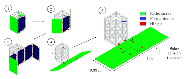
The Polytechnique Montreal is conducting research on attaching a SAR antenna using Reflect-Array technology to a 12U platform [9]. The antenna of 1 m × 1/3 m is attached to three sides using hinges and is deployed on orbit (Fig. 10). Ground tests have achieved a resolution of 50 m × 50 m using such a SAR antenna.
3.2. RF Communication
Communication between ground stations and satellites, or between satellites themselves, is commonly accomplished by radio-frequency wave. NASA’s satellites typically connect to the NASA Near Space Network using the S-band (2~4 GHz), X-band (8~12 GHz), and Ka-band (27~40 GHz). Moreover, larger satellites have utilized higher frequency bands such as Ku-band (12~18 GHz), K-band (18~27 GHz), and Ka-band (27~40 GHz) for inter-satellite link. Current CubeSats are usually equipped with antennas capable of transmitting and receiving in VHF (30~300 MHz), UHF (0.3~1 GHz), L-band (1~2 GHz), and S-band.
Apart from the difference in wavelength bands, the technology used for radio communication is the quite similar for general satellites and CubeSats. Companies such as GomSpace, Nanocom, and Syrlink are already manufacturing and selling radio communication components for CubeSat, including transceivers, mixers, filters, and power amplifiers, with a variety of options. Therefore, to apply radio-frequency technology to communication between ground stations and CubeSats, one can consider importing such products with appropriate link and power budget.
However, there remain some limitations when applying radio-frequency communication to CubeSat for space national security. A sufficient size of antenna for Radio-frequency communication is critical to ensure signal strength and SNR, but there exists limitation in simply increasing the size of antenna on the CubeSat platform to just enhance antenna gain. Although patch antennas have been developed and deployable antennas are being researched and developed, these technologies are not yet mature enough. Also, CubeSat platform has distinct limitation in continuously communicating the large amount of data generated from reconnaissance.
The most significant issue in radio-frequency communication in CubeSat for space national security is the potential of eavesdropping due to the broad bandwidth of the radio-frequency signal. The width of a radio signal is typically defined based on the point where the signal strength is half (-3 dB), and conventional radio-frequency communication has a beamwidth of more than 15°. This means that, assuming a CubeSat mission operating at an altitude of 500 km, a signal corresponding to half the energy of the transmission can be reliably received from 65km away from the intended ground station. The fact that whoever tens of kilometers away could receive the radio signal transmitted by CubeSats on a national security mission represents a critical security flaw, which could be addressed by installing a communication security module which applies encryption.
3.3. Laser Communication
Laser communication has been attrating attention in satellite communication system. laser has a beamwidth less than 0.1°, which is significantly narrower compared to radio-frequency wave. This means that a signal transmitted from an altitude of 500 km can be received within an area of only 1km, substantially reducing the risk of sensitive information theft compared to radio-frequency communication. However, due to the narrow beamwidth, it is imperative that the ground station’s antenna precisely tracks the CubeSat during laser communication to maintain high Signal-to-Noise Ratio (SNR), and CubeSat should also accurately point to the ground station while transmitting laser. The permissible pointing error is less than 10 arcseconds, and to achieve this, the CubeSat performs two steps of pointing.
Due to the limitations on the volume of CubeSat platform, it is not feasible to install gimbals used for pointing in conventional satellites. Instead, CubeSats execute coarse pointing through attitude control of CubeSat body itselt, where reaction wheels operate as actuators. The pointing accuracy can be enhanced by equipping multiple attitude determination sensors, such as star trackers. The remained pointing error not corrected by coarse pointing can be compensated with Fine Pointing by precisely controlling the direction of laser using a Fast Steering Mirror (FSM).
The most significant advantage of laser communication over radio-frequency communication is the reduction in signal energy loss, utilizing a beamwidth more than 100 times smaller than radio-frequency wave, which allows for a revolutionary reduction in antenna diameter. Equation (1) shows that the shorter wavelength of laser results in less energy loss at the receiver and constraints in choosing antenna diameter is resolved.
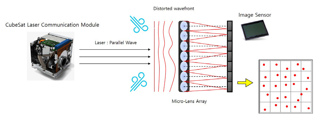
One must consider that laser communication can also be affected by the atmosphere when data rate is high, leading to aberration or distortion. If the wavefront of the received laser is distorted, ther signal might not maintain enough power for post-processing. To address this, the adaptive optics, including wavefront sensors and correction models, in both directions between the ground station and the CubeSat laser communication module, as illustrated in Fig. 11, is introduced and being developed.
The laser communication CubeSats in development can be summarized as follows.
3.3.1. OCSD Mission
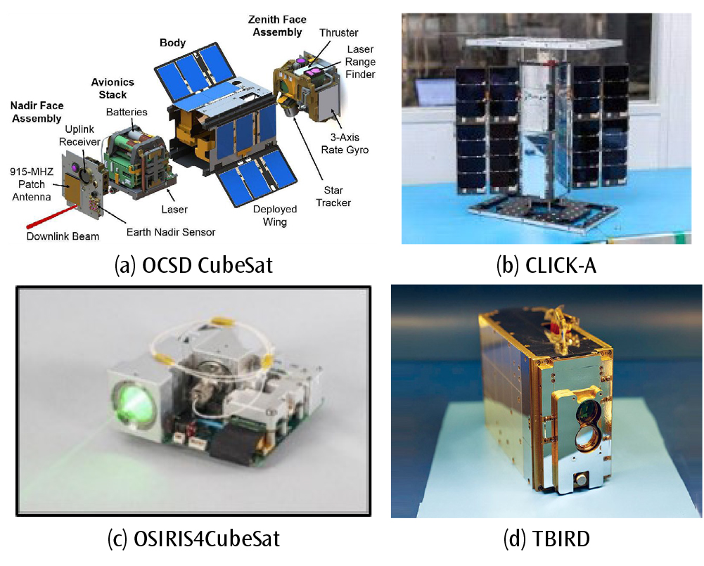
The OCSD (Optical Communications and Sensor Demonstration) project aims to develop and leverage low-power laser communication system. The whole configuration of the OCSD CubeSat is shown in Fig. 12(a). The laser communication module of this mission is developed in a 1.5U size and successfully performed communication at a speed of 200 Mbps in conjunction with a telescope of 40cm aperture at the ground station [5]. The OCSD CubeSat shows a pointing accuracy less than 180 arcseconds with two star trackers. The development team plans to further upgrade the laser communication module, particularly by enhancing the performance of the attitude control, with the expectation of achieving downlink rate of 2.5 Gbps.
3.3.2. CLICK-A
CLICK-A, an acronym for “CubeSat Laser Infrared CrossLink,” shown in Fig. 12(b) is a 3U CubeSat equipped with a 1.2U laser communication module that performs fine pointing with MEMS FSM [10]. Orbiting at an altitude of 400 km, CLICK-A successfully achieved downlink laser communication at 10 Mbps in cooperation with a ground telescope of 28cm aperture. CLICK-B and-C are also planned for launch in 2024, aiming for laser communication rate of 20 Mbps.
3.3.3. OSIRIS4CubeSat
OSIRIS4CubeSat is the name of the laser terminal mounted on the CubeSat of the PIXL-1 (Photo Images Cross Laser) mission (Fig. 12(c)). This module utilizes MEMS FSM and 4QD (4-quadrant diode) to perform fine pointing [11]. The ground station received a 100 Mbps laser signal transmitted by OSIRIS 4 using a telescope of 60 cm aperture.
3.3.4. TBIRD Terminal
TBIRD means Tera-Byte Infrared Delivery. As shown in Fig. 12(d), TBIRD terminal is a 2U laser communication module mounted on NASA’s 6U CubeSat PTD-3 (Pathfinder Technology Demonstrator 3). The ground station utilized a 1 m aperture telescope and introduced adaptive optics to enhance the quality of the received signal. 100 Gbps laser communication was achieved in 2022 [12].
Additionally, there exists a 1U-sized laser communication module in the commercial CubeSat market, named CubeCAT (Fig. 13), which is developed through a collaboration between Hyperion Tech. and TNO. To date, no missions have been reported for this module. It operates at a voltage of 5V and consumes less than 20W of power. With fine pointing accuracy of 600 arcseconds and a pointing direction recognition error of 60 arcseconds, while it may be deployed for general CubeSat missions, it is yet unsuitable for CubeSat for space national security which requires a pointing accuracy less than 10 arcseconds.
3.4. Summary of Technologies for Space National Security CubeSat
In this section, the technologies which have to be developed for space security CubeSat are summarized among the technologies identified in earth observation, SAR, and laser communication.
3.4.1. EO
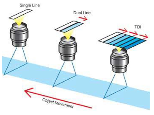
Conventional CubeSats operate EO payloads with apertures less than 10cm, achieving resolution of about 3~5 m in LEO. For CubeSats developed with national security objectives, EO payloads are required to have a resolution of at least 1m to detect military movements early. However, it is challenging to secure enough light-gathering power and SNR with standard optics to achieve 1m resolution. This challenge can be addressed by introducing technologies that increase the relative exposure time. Examples of such technologies include the Time Delay Integration (TDI) and forward motion compensation techniques like Yaw Steering, which compensates for the ground track displacement caused by Earth’s rotation during the exposure time.
TDI sensors are composed of multiple stages, as illustrated in Fig. 14. When certain target moves at a constant speed, the signal output from the first stage is accumulated. As the target slightly moves to the second stage, the output of the second stage is added to that of the first stage. This process is repeated up to the last stage, resulting in an image with increased sensitivity compared to a general snapshot.
Due to Earth’s rotation, even in the short moment a satellite captures certain target point, the target appears to move in a direction combining the opposite satellite’s velocity and the Earth’s rotation vector. To obtain a sharp image using TDI sensors, the direction of capture must align with the relative direction of the ground target movement. Therefore, the satellite must perform attitude maneuver during the imaging time. By rotating the satellite at a specific rate around the axis towards the Earth’s center, it is possible to counteract the Earth’s rotation. This technique is known as Yaw Steering [13]. Since the algorithm is not complex, it is definitely feasible to implement Yaw Steering in the attitude control of EO CubeSats as well.
3.4.2. SAR
At present, technologies for mounting SAR payloads on 3U and 6U CubeSat platforms is not yet mature, particularly in terms of antenna stowage and deployment, as well as thermal and power management. However, if the implementation into 18U CubeSat platform is considered, the following technological developments would be required. First, technologies which compensate and correct structural defects and errors occurring during deployment of foldable antenna is necessary to apply wide antenna. As SAR payloads are not simply for transmission or reception but rather for analyzing signals reflected back from the surface, precise calibration process should be developed if deploying antenna is attached to CubeSat platform.
Moreover, because SAR antennas transmit and receive large amount of data, they require high instantaneous power and generate considerable local heat. It is essential to conduct repetitive thermal and power management tests, utilizing thermal vacuum chambers, to verify operational stability of CubeSat SAR payload in space environment.
3.4.3. Laser Communication
For space national security CubeSats, security in communication must be a primary consideration. Laser with a beamwidth of less than 0.1° can only be received within a radius of 1km when transmitted from LEO, thereby offering superior security. Given that laser communication technology is not yet fully mature in the CubeSat field and there are no commercially available modules with proven space mission heritage, the development of own laser communication terminal is necessary. To ensure laser communication with sufficient intensity and SNR using narrow beamwidth laser, it is crucial to develop pointing technologies. Enhancements in the performance and the number of sensors such as star trackers, improvements in filtering (or, estimation) techniques, and an increase in the number of reaction wheels are feasible methods to enhance the performance of the Attitude Determination and Control System (ADCS). Additionally, developing and refining algorithms for operating FSM is essential to achieve precise fine pointing of laser.
4. SUGGESTION FOR NATIONAL SPACE SECURITY CUBESAT SYSTEM
4.1. Analysis of Characteristics of Small Satellites Constellation System
This study analyzes the small satellite constellation currently under development by Satellite Technology Resarch Lab (SaTReC). The project involves the development of 11 satellites under 100 kg, aiming to produce one prototype of ITAR-Free satellite, followed by the development and launch of an additional 10 satellites. The design concept focuses on lightweight, low power, and cost-effective solutions, introducing Commercial Off-The-Shelf (COTS) components considering a mission lifespan of three years.
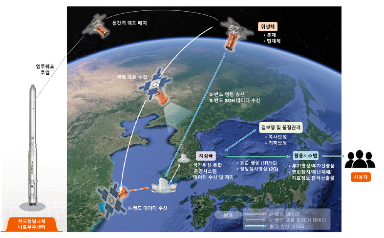
The primary mission of this constellation is to acquire high resolution optical images of target area, with the goal of maximizing responsiveness to sudden disasters and emergencies through wide-area real-time observation (Fig. 15). The satellites are planned to orbit at an altitude of 500 km in sun synchronous orbits (SSO), arranged in orbital planes with Local Time of Descending Node (LTDN) at 10:30 and 13:30, considering cooperative operation with KOMPSAT.
The swath-width of the EO image is 10 km, with resolution of 0.8 m in panchromatic and 3.2 m in color. Operation modes can be divided into nadir and tilt capture. Nadir direction allows for capturing images perpendicular to the Earth’s surface, enabling imaging an average of 3-4 times of the Korean Peninsula per day from polar orbit. However, to enable continuous monitoring of the Korean Peninsula, tilt shooting is employed, allowing the satellites to rotate up to 30° in the roll direction, doubling the capturing frequency to an average of 7-8 times per day compared to nadir one. The downlink data rate is 600 Mbps.
Research is ongoing to implement automatic detection system using AI for downlinked images which captures Korean Peninsula, and to introduce technology for converting geometrically distorted images from roll tilt into orthophotos as viewed from a nadir direction.
The launch of the small satellite constellation system is planned through a Korean launch vehicle, with foreign launch vehicles as alternatives if Korean launch vehicle is unavailable. The plan involves completing the constellation in three launch steps, each step launches 5 satellites at a time following the first prototype satellite launch.
4.2. Concept of Earth Observing CubeSat System
Assuming CubeSat constellation in SSO having an inclination over 90°, in order to carry out reconnaissance Korean peninsula, EO payload of CubeSat should be capable of capturing swath-width of more than 280 km. The small satellite constellation, mentioned in the previous section, consisting of 11 satellites, can photograph the Korean Peninsula 7-8 times a day through roll tilt. This indicates that, during daytime, a maximum swath of 80 km can be covered by appropriately setting orbit plane and interval between satellites. Thus, surveilling the entire Korean Peninsula within 24 hours remains unfeasible by this constellation. However, strategically deploying a cluster of EO/IR CubeSats, which are relatively quick and cost-effective to produce and launch, could significantly expand the coverage for photographing the Korean Peninsula. Assuming a swath-width of 32 km for the CubeSat EO/IR payload, Equation (2) indicates that at least 15 CubeSats are needed to scan an area of interest spanning 300 km in width during daytime. This is the minimum number of CubeSats based on the assumption that orbits of each CubeSat are ideally set so that imaging areas are not overlapped. To increase the frequency of surveillance over certain area during daytime, additional CubeSats could be deployed to the constellation.
SSC : Small Satellite Constellation
It is assessed that the same imaging swath of 32 km, as developed for the EO payload of Space SCANeR by KASI, could be applied to the EO/IR payloads of CubeSat for space national security. The technical maturity for immediately deploying SAR payloads on CubeSats is considered very low. However, the development and testing of prototype CubeSats as platforms to test the performance of deployable antennas and processors for SAR payloads, aiming for future application on space security CubeSats, are considered as a viable option.
4.3. Concept of Communication CubeSat Constellation
First, the construction of a satellite communication network can be suggested as the concept of communication CubeSat. However, building an internet network with a CubeSat constellation seems impractical. A prominent example of a satellite communication network is SpaceX’s Starlink, which plans to deploy around 12,000 satellites in 1st generation and 30,000 in 2nd generation, each weighing around 260 kg, with continuous launches still underway. Constructing a global satellite communication network with conventional 3U and 6U CubeSat platforms is considered unrealistic due to the limitation of payload capacity and the saturation satellites in Earth’s orbit.
Nonetheless, CubeSats could be utilized to add a security layer in communications between conventional satellites and ground stations by acting as intermediaries. Sensitive image data captured by satellites could be transmitted to nearby CubeSats using relatively weak signal intensity during image capture, and then CubeSats could imidiately downlink the data to ground stations by laser communication, significantly mitigating the risk of eavesdropping. The reason conventional satellites do not directly apply laser communication is to perform imaging and downlink simultaneously. Laser communication requires precise antenna pointing, and driving gimbals to downlink to ground stations while conducting reconnaissance could compromise attitude control stability and decrease image quality. Therefore, a reconnaissance process can be proposed that transmitting RAW data to nearby CubeSats using weak radio wave and then these CubeSats immediately downlink it to ground station.
The target performance for laser communication CubeSat is set based on currently operational CubeSat. The CUBELCT laser communication module mounted on the PIXL-1 mission CubeSat, which is 0.3U size and consumes 8W of power, can uplink/downlink at rates of 1 Mbps / 100 Mbps, respectively [11]. Laser pointing is accomplished through the CubeSat’s attitude control and FSM, with the latter capable of performing pointing accuracy within a range of 1°.
4.4. Security System of Communication between CubeSats and Ground Station
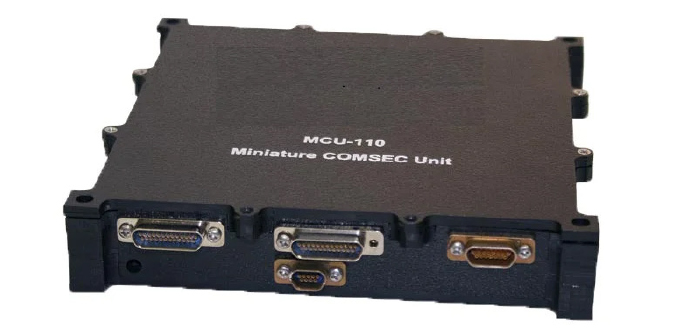
It is common not to equip encryption devices in radio communication module for simple Earth observation satellites. However, as the number of satellites in LEO increases and many CubeSats begin to employ COTS components and open-source software, the risk of third parties intercepting and stealing communication data is being increased. Consequently, there is a growing need to introduce encryption systems into radio communication for CubeSat operated for national security purposes, such as surveillance and reconnaissance, to prevent adversaries from stealing sensitive data. While several commercially available encryption modules for satellite radio communication exist, as illustrated in Fig. 16, these modules present challenges for integration into the 10 cm unit CubeSat platform due to their size, high power consumption, and the reduction in data rate to several Mbps during encryption and decryption processes.
Mounting laser communication module to CubeSat could be considered as an alternative to encryption module because, in LEO, only receivers within 1km or less can receive downlinked signal from CubeSats. This inherent characteristic of laser communication provides a level of security, making the development and deployment of laser communication module a viable approach for enhancing the security system of CubeSat constellation.
4.5. Complementary Utilization of Small Satellites and CubeSats
Small satellites of the 100 kg cannot be launched in multiples by a single launch vehicle and are designed with narrow swath-width for their EO payloads to achieve precise observation. Conversely, CubeSats can be deployed in multiples in a single launch, and despite the lower resolution due to the limitations of EO payload’s volume, they can offer wider swath-width. Even with the development and integration of high-resolution EO payloads for CubeSat, continuous and efficient operation may be challenging due to duty cycles of components, long period for downlink, and power and thermal management issues. Small satellites must wait for revisit cycles for communication with ground stations, but the orbital plane distribution of a CubeSat constellation can significantly reduce the overall revisit cycle. Considering these aspects, two strategies shown in Fig. 17 are proposed where small satellites and CubeSat constellations complement each other’s limitations.
First, the CubeSat constellation’s global coverage is expanded by designing orbits in polar or SSO with various Right Ascension of Ascending Node (RAAN). The CubeSat constellation continuously monitors target areas using EO payloads with wide swath-width and low resolutions. If a single CubeSat detects anomalies such as rocket launches or large scale military movements, it can directly downlink to the ground station or transmit to a nearby small satellite. Subsequently, the small satellite, either autonomously generating an operation scenario or immediately uplinked by the ground station, can conduct reconnaissance in detail with its high resolution EO payload. By preemptively detecting threats with low resolution observation from CubeSat constellation and immediately deploying small satellites for reconnaissance, the capability to respond to security threats can be significantly enhanced.
Next, in the event of an emergency national security situation where real-time observation data from small satellites becomes saturated, making rapid downlink impossible, CubeSat constellations can be utilized. In a large scale military scenario, multiple EO payloads and SAR equipped on conventional satellites will be activated, and it would be nearly impossible to downlink all the stored RAW data during the limited ground station visit time. Large amount of data stored in small satellites can be partitioned and transmitted to nearby CubeSats, which then use laser communication to downlink the partitioned data to ground stations. This approach not only extends the brief ground station link times available to small satellites but is also expected to dramatically reduce the time required to downlink all data.
5. PERFORMANCE ANALYSIS OF EARTH OBSERVING PAYLOAD
5.1. SAR and Hyper-spectral Sensor
5.1.1. Synthetic Aperture Radar (SAR)
To date, there have not been reported CubeSat missions utilizing SAR, with a few cases exploring the deployment mechanisms of foldable antennas on relatively large CubeSat platforms of 12U and above. SAR payloads, utilizing a wide bandwidth and exhibiting higher power consumption and heat generation compared to other payloads, are recognized to have a low level of maturity for CubeSat yet. However, drawing from the achievements of small satellites such as the 70 kg ICEYE and Umbra, which attained resolutions of 50 cm and 25 cm respectively, it is conceivable that with developments in reducing power requirements and revolutionary improvements in thermal management, SAR payloads could be introduced and tested on CubeSat platform using deployable antennas and solar panels.
5.1.2. Hyper-spectral Sensor
Hyperspectral sensors typically refer to optical systems capturing images in more than 37 bands. Storing large volumes of data while capturing two-dimensional terrain across multiple wavelengths results in significant local heat generation, similar to SAR. Implementing hyperspectral sensors on CubeSats necessitates high-speed data storage and processing capabilities to handle large data volumes. Additionally, given the distinct thermal environmental limitations of CubeSat platforms, the development of sensor structures specific for CubeSat, thermal management systems, and testing protocols is required.
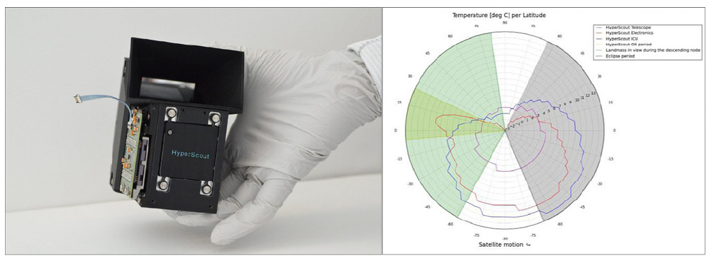
One notable instance of hyperspectral sensor on CubeSat is GomX-4 developed by GomSpace and ESA, which mounts a hyperspectral sensor named HyperScout. This sensor is capable of capturing 45 spectra with 15 nm intervals in 400-1000 nm, achieving a resolution of 70m from swath-width of 200 km with a FOV of 23°. HyperScout weighs 1.1 kg within a 1U volume and consumes 11 W of power. It successfully passed thermal vacuum tests, maintaining subsystem temperatures within appropriate ranges during the mission, as shown in Fig. 18.
5.2. Concept and Verification Research of Deployable Optical CubeSat in KAIST
This section introduces the concept design and experimental validation through prototype of unit separated optical CubeSat conducted by the Smart Structures and Hardware Systems Lab at KAIST.
5.2.1. Conceptual Design of Deployable CubeSat
The mission of the Deployable CubeSat (DCS) is Earth observation, with the optical system comprising a telescope and an image detector. The performance of the optical payload is significantly influenced by the diameter and focal length. However, the small size of CubeSats presents spatial limitations, making it challenging to utilize large optical systems. Therefore, this study aims to design a CubeSat capable of orbital separation using deployable structures to achieve a long focal length. The study proposes separating an 8U CubeSat into two 4U platforms. For the conceptual design of mission equipment, complex internal subsystems were not considered.
A general scissors-type deployable structure is applied, and a Cassegrain telescope is assumed to be inside. As can be seen in Fig. 19, convex and concave mirrors are positioned at the center of the upper and lower 4U frames, respectively, and the deployment process is as shown in Fig. 20. The design parameters for the stowed and deployed states are as listed in Table 2.
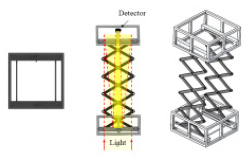
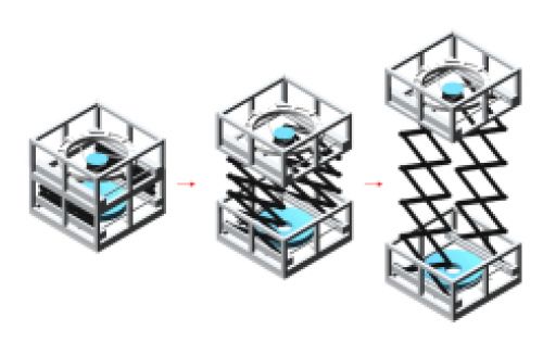
TABLE 2.
Structural parameters of DCS
5.2.2. Mathematical Model and Performance Analysis
In this study, to analyze how much the concept of unit-separable CubeSat improves the quality of image, the performance of an optical system of a Reference CubeSat (RCS) with the same size and magnification (3.192) before deployment was compared. The mission altitude was set at 600 km. The main optical parameters of DCS and RCS are shown in Table 3.
TABLE 3.
Optical parameters of DCS and RCS
Ground Sample Distance (GSD), an important requirement of optical system, refers to the ground distance represented by one pixel and is calculated as Equation (3).
Next, the Modulation Transfer Function (MTF) represents the resolution of optical system. Higher MTF results in clearer images. MTF is expressed as Equation (4). MTF of DCS and RCS are obtained using radial spatial frequency and cut-off frequency as Table 4, assuming the wavelength is at the maximum of the visible light, 800nm.
Although the unit-separable CubeSat exhibits an improved GSD compared to RCS, there is a trade-off in terms of MTF. However, most optical payloads including detector require MTF of more than 7%, and telescopes alone have a requirement of more than 11%. Therefore, it is observed that the unit-separable CubeSat meets common MTF requirements.
5.2.3. Verification of Prototype by Experiment
A prototype equipped with a simple refractive optical system was constructed, and its performance was verified through experiments. Optical components such as detectors and lenses were all sourced from commercial products (COTS). For example, detector is an monochrome XMOS image sensor with pixel array 1920 × 1200. The prototype of DCS is composed of a lens unit and a detector unit, connected and separated by a deployable scissors structure, as shown in Fig. 21(a). Fig. 21(b) displays an alignment jig for correcting alignment errors after full deployment. In this study, manual compensation of alignment errors was carried out. Fig. 21(c) illustrates the stowed and deployed DCS, with the stowed state corresponding to approximately 2U.
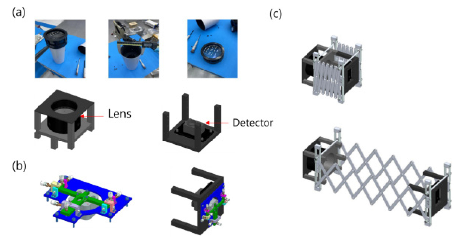
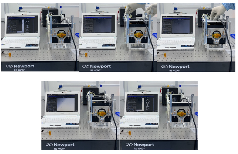
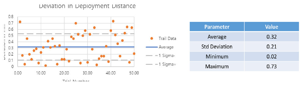
Fig. 22 depicts the deployment test process of DCS prototype, with the monitor on the left displaying the image from the optical system in real time. Furthermore, Fig. 23 shows the variance in deployment distance in repetitive tests, confirming that the image quality does not significantly deteriorate despite repeated deployments of the DCS prototype.
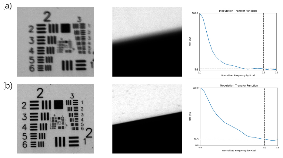
As shown in Fig. 24, immediately after deployment, the image may be unclear and exhibit low performance due to alignment error. However, it was verified that sufficient performance, approaching that of conventional optical systems, could be achieved through calibration. This confirms the feasibility of the unit-separated concept for practical implementation.
5.3. Development Status of Laser Communication Module for CubeSat in KAIST
Spacecraft Prototyping Laboratory at KAIST is currently developing a laser communication module for CubeSat. This section introduces the development process and ground test.
5.3.1. EM of Laser Communication Module
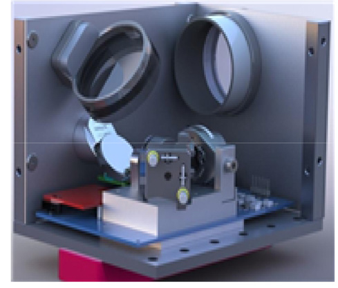
Laser communication moduyle for CubeSat was designed in 1.5U, with a pointing system constructed only for downlink. The 3D model designed using SolidWorks is shown in Fig. 25. Two mirrors were installed to accommodate a 5 cm diameter optical antenna within the CubeSat frame, satisfying a focal length of 15 cm. FSM, Quadrant Photodiode (QPD), and collimator were positioned very closely to minimize the distortion that could occur while the laser receiving.
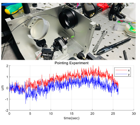
The manufactured payload underwent a pointing test. It performed pointing control upon receiving a visible beacon signal acting as a ground station and transmitted an IR signal. The pointing accuracy derived from measuring the jitter of the IR signal showed a precision of approximately 4 arcseconds (Fig. 26).
5.3.2. EM of CubeSat body
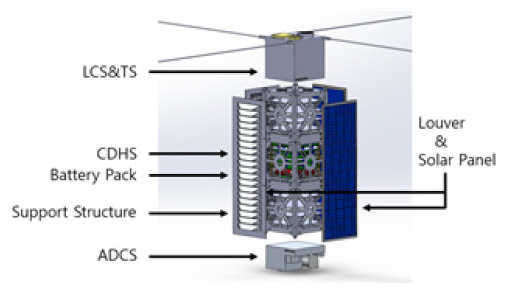
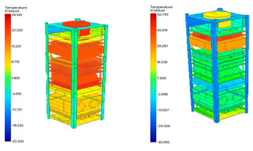
A 3U CubeSat platform was designed for laser communication. The CubeSat comprises a 1.5U laser communication payload at the top, 0.8U of electronics in the middle, and about 0.6U for the Attitude Determination and Control System (ADCS). The overall configuration of CubeSat structure is designed as seen in Fig. 27. The configuration of CubeSat was designed using SolidWorks, and thermal and vibration analyses were conducted using ANSYS, as described in Fig. 28. The equipment maintained operational temperatures with a margin of more than 10°C during the test, and vibration analysis under the quasi-static load environment defined by the Falcon 9 launch vehicle satisfied the launch requirements.
5.3.3. Attitude Control Research using Telescope Mount
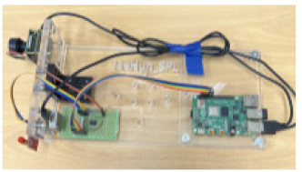
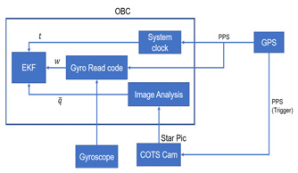
A ground test bed for the attitude determination (AD) using star trackers and gyroscopes was developed (Fig. 29). This equipment can generate the desired attitude by RST-135 mount. The structure of the attitude determination algorithm is as illustrated in Fig. 30. Real-time experiment utilized the PPS signal from a GPS receiver to synchronize the time of OBC and the gyroscope and to determine the moment of attitude capture and image of star tracker.
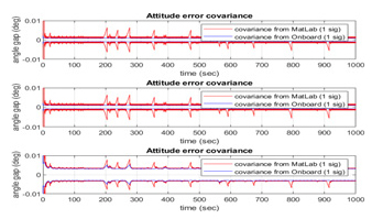
When the AD testbed was mounted on the RST-135 and subjected to changes in attitude and angular speed by mount, attitude and error estimation using an extended Kalman filter yielded attitude error estimates as shown in Fig. 31.
5.3.4. Performance Test of Optical Ground Station
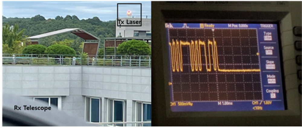
A simple optical table was installed at the eyepiece of the telescope to construct a 9 kg communication system. The configuration of the optical ground station is depicted in Fig. 32. The laser entering through the eyepiece is reflected from FSM and split into two paths at the beam splitter, directed toward the avalanche photodiode and the quadrant sensor.
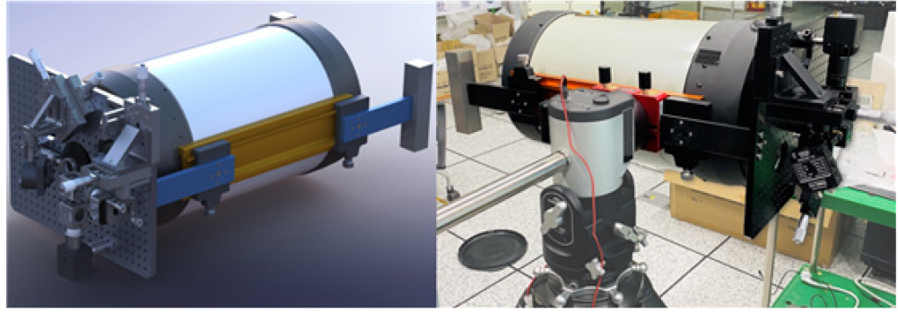
Outdoor experiments were conducted to verify the performance of the laser communication system, as shown in Fig. 33. Laser device was installed at the ground station, and data of 1Mbits were transmitted using a UART protocol at approximately 7.6 Kbps.
6. CONCLUSION
This study has introduced the trend of CubeSat, along with the technologies related to Earth observation CubeSats, and investigated radio and laser communication. Additionally, the characteristics of small satellite constellation were summarized, and complementary utilization plans with CubeSat constellation were proposed. Subsequently, the research and development status of laser communication modules and unit-separated Earth observation CubeSats were introduced, and their performance limitations were analyzed.
For space security purposes, it is assessed that EO/IR Earth observation and laser communication technologies are practical for CubeSat. While SAR and hyperspectral sensors are undoubtedly effective equipment for area monitoring, their size and weight pose significant challenges for deployment on CubeSat. Once antenna stowage and deployment techniques become mature, CubeSat could potentially serve as test platform for such technologies.
Conventional Earth observation satellites typically carry high resolution optical payload with limited swath-width. Moreover, deploying multiple satellites into orbit takes a lot of time and cost, rendering frequent revisits to reconnaissance areas and ground stations impractical. CubeSats equipped with EO/IR optical systems are considered effective in overcoming the limitations of swath-width and revisit cycles faced by small satellite constellation. This research proposed two complementary utilization plans for CubeSat constellations and small satellites.
Introducing laser communication between CubeSats and ground stations not only significantly enhances the security of sensitive data by limiting the locations where signals can be received by narrow beamwidth, but also effectively reduces the latency between high resolution reconnaissance imaging and downlinking by small satellite constellations.
Lastly, the unit-separated optical CubeSat and the laser communication module for CubeSat currently under development at KAIST were introduced. It is anticipated that integrating these independently developed technologies into the development of CubeSat for security purposes will achieve the desired imaging and communication requirements.
